background image

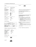
1.0 TECHNICAL SPECIFICATION

General

Dimensions (WxLxH):

19.3 x 16.1 x 3.0 cm
7.72 x 6.44 x 1.2 inches

Weight:

0.824 kg / 1.81 lb

Power supply:

DC 9V 2.2A

Power consumption:

30W

Operating temp. range:

0 - 50˚C (32 ~ 122˚F)

Laser wavelength:

650nm

Video system:

NTSC / PAL / AUTO

Frequency response:

20Hz ~ 20KHz ± 1dB 

Signal/noise ratio:

85dB

Audio dist noise:

-80(1KHz)

Channel separation:

85dB

Dynamic range:

80dB

Output
Audio out (analog audio):

Output level: 2V ± 10%

Load impedance:

10K

Video out Output level:

1Vp - p ± 20%

Load impedance:

75

Current consumption

DC-IN SUPPLY (9.0V)

Battery Charging Current

1.2A typ.

BATT. SUPPLY (7.2V)

Power Off

0A

Playback with TFT on

<1.2A typ.

Playback without TFT on

<600mA

Battery playtime

>2.5hrs

Headphone out (headphone output load 2x16ohm)

Maximum output power:

>10mW

Frequency response:

20Hz - 20kHz

SNR (A-wght):

80dB typ.

THD (1kHz):

<1%

Left-Right Channel
Separation:

32dB typ.

Left-Right Channel
Balance:

1dB

Supported disc type

DVD video discs:

Audio CD:

In addition, this unit can play DVD+R & DVD+RW and CD-R &
CD-RW that contains audio titles or MP3 or JPEG files.

You cannot play disc other than the above listed.
(CVD, CD-ROM, CD-Extra, CD-G and CD-I discs cannot be
played on this DVD player)

Software upgrades

For the best performance of your DVD Portable. Check

www.philips.com/support

 for latest software

upgrades available.

To check the software version of your DVD Portable.
1.

Press the SETUP key to enter the setup menu.

2.

Press RETURN and then press 1. 2 and 3 on the
remote control.

3.

The display will show the software version as the
date of which the software was built on the bottom
of the screen. E.g. 050303

Procedure on how to upgrade the software of the DVD
Portable
1.

Download the latest software from the Philips
support site.

2.

Unzipped the files and then burn it onto a CD ROM
then playback the CD ROM on the DVD Portable.

Pixel specification

<= 4 (max. 1 bright dots and 3 dark dots)

Video CD:

Summary of Contents for PET700

Page 1: ...agram 7 Electrical Diagram 8 Component Layout 9 Exploded View Diagram Service Part List 10 Revision List 11 Service Manual OSD TEST CONFIGURATION SETUP Copyright 2005 Philips Consumer Electronics B V Eindhoven The Netherlands All rights reserved No part of this publication may by reproduced stored in a retrieval system or transmitted in any form or by any means electronics mechanical photocopying ...

Page 2: ...annel Separation 32dB typ Left Right Channel Balance 1dB Supported disc type DVD video discs Audio CD In addition this unit can play DVD R DVD RW and CD R CD RW that contains audio titles or MP3 or JPEG files You cannot play disc other than the above listed CVD CD ROM CD Extra CD G and CD I discs cannot be played on this DVD player Software upgrades For the best performance of your DVD Portable Ch...

Page 3: ... caso di non osservazione della più grande cauzione alla loro manipolazione Durante le riparazioni occorre quindi essere collegato allo stesso potenziale che quello della massa dell apparecchio tramite un braccialetto a resistenza Assicurarsi che i componenti e anche gli utensili con quali si lavora siano anche a questo potenziale Pour votre sécurité ces documents doivent être utilisés par des spé...

Page 4: ... operates properly after replacement if it was subject to electrostatic discharge during replacement its life might be shortened When replacing use a conductive mat soldering iron with ground wire etc to protect the laser diode form damage by static electricity And also the LSI and IC are same as above Soldering iron with ground wire or ceramic type Ground conductive wrist strap for body Conductiv...

Page 5: ...xists the fault must be located and corrected Repeat the above test with the DVD VIDEO PLAYER power plug reversed NEVER RETURN A DVD VIDEO PLAYER TO THE CUSTOMER WITHOUT TAKING NECESSARY CORRECTIVE ACTION READING SHOULD NOT EXCEED 0 3V DVD VIDEO PLAYER AC OUTLET AC VOLTMETER Test all exposed metal Voltmeter Hook up for Leakage Current Check 0 15uF 150V AC 1500 10W 5000 per volt or more sensitivity...

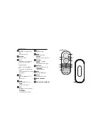
Page 6: ...WER OFF Switches the player on off DC IN 9V Power supply socket 3 0 INSTRUCTIONS FOR USE 1 2 3 4 5 6 10 7 8 Up down left right cursor OK Confirms selection Pause playback Press twice to stop playback For previous or next chapters tracks or titles Starts resumes playback OPEN Opens disc door to insert or remove disc VOLUME Volume control Headphones jack 9 A V OUT Audio video output jack DVD PLAYER ...

Page 7: ... VCD menu page ANGLE Selects DVD camera angle SUBTITLE Subtitle language selector LANGUAGE Language selector MENU Displays MENU page SETUP Enters SETUP menu Remote Control Up down left right cursor Confirms selection On Screen Display on off INFRA RED PORT BATTERY COMPARTMENT 10 11 12 13 14 Pause playback Press twice to stop playback For previous or next chapters tracks or titles Search backward o...

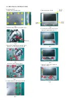
Page 8: ...ain board as Fig 3 4 Disconnect the DVD driver and main board Fig 3 4 Remove key board and other parts as Fig 5 Fig 5 5 Remove top cover as Fig 6 Fig 4 Remove DVD driver and main board Fig 6 6 Disconnect the speakers and IF board Remove IF board shield as Fig 7 8 7 Fig 7 Remove IF board and HV board and LCD TFT as Fig 9 Fig 9 remove screws remove screws remove screws Fig 8 ...

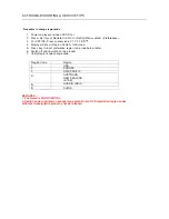
Page 9: ...w Region Code 2 for Europe 5 Press key to input preference region code see below table 6 Switch off and re switch on the product Verify Region code change done 7 Region Code Region 1 USA 2 EUROPE 3 ASIA PACIFIC 4 AUSTRALIA NEW ZEALAND LATAM 5 RUSSIA INDIA 6 CHINA REMARKS 1 Password is CONFIDENTIAL 2 Region code is printed on product type plate Due to DVD legislation region codes different to assig...

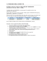
Page 10: ...940 000 05107 5110G 060210 13 52 SQPN 4 New IC PCBA and software version is implemented from SN 010608000001 on wk608 Procedure on how to upgrade the software of the DVD Portable 1 Download the software from P4S website refer G SI PI 06 006 2 Unzip the attachment to get the bin file named H3SUD 3 Burn the bin file onto a CD ROM and make sure rename the disc name to SHINCO Do not allow multi sessio...

Page 11: ...eral Service Information BG ES PI 06 032 The phased out HV and FUNCTION PCBA board The 12NC is shown as below 994000004201 PET705 HV PCBA 994000004202 PET705 FUNCTION PCBA The phased in HV and FUNCTION PCBA board The 12NC is shown as below 996500040947 PET705 HV PCBA NEW 996500040948 PET705 FUNCTION PCBA NEW ...

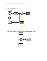
Page 12: ...n set to customer yes start set OK Check if the power and play button OK replace connector and switch unit replace MAIN BOARD go to other SYMPTOM no yes yes no replace DVD drive SYMPTOM NO IMAGE OR SOUND COMES OUT FROM THE EXTERNAL OUTPUT start Check operation of the DVD drive Does the DVD drive work yes no Replace the main board or the connector ...

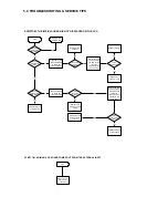
Page 13: ...nnector harness broken Replace broken harness yes Remove the LCD cover and plate of the LCD unit to check the connector of the FL harness Is the connector OK no Repair connector Replace FL inverter or LCD no yes Is the connector broken Replace LCD harness or main board yes Remove the LCD cover and plate of the LCD unit to check the connection of the harness to the LCD unit no Is the connection OK ...

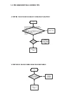
Page 14: ...tall a good battery does the LED lights up orange while the AC adapter is connected and does the DVD drive operate OK NOTE For this check use a battery which is not fully charged because the LED does not light when the battery is fully charged Before this check make sure other function work correctly no SYMPTOM NO SOUND COMES FROM THE HEADPHONES start Replace main board yes Insert a good headphone...

Page 15: ...re the connection of the DVD drive and main board Not OK Pick up lens light up OK Insert a DVD disc and turn on the power What is the reaction of the DVD drive The DVD drive works but the initializing operation of the optical pick up lens does not start the optical pick up lens operates twice or abnormal noise sound Replace DVD drive or main board DVD drive does not work The operation of the DVD p...

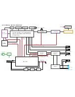
Page 16: ...PU mechanism DRIVER BA5888 8M FlashROM MX26LV008BTC 55G 64M SDRAM HY57V641620ETP H TC4W53 27MHz AUDIO D A CS4345 UPD5100 TFT MONITOR AUDIO AMP AZ4558 HWD4863 HIGH VOLTAGE ASS Y 74HCU04 27MHz VIDEO OUT AUDIO OUT PHONE OUT SPEAKER LOUT SPEAKER ROUT L R L R DRIVER 5V 5V AUDIO 5V 5V 3 3V 1 8V AUDIO 5V TFT POWER 3 3V 5V 2 5V 15V 16V 9V COAXIAL OUT DC 9V OSCILLATOR OZ9RR 14 31818MHz ...

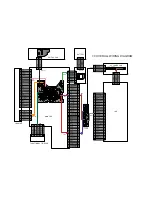
Page 17: ... 5 4 3 2 1 XS1 XS008 XS6 FUNCTION BUTTON PCB LOADING MAIN PCB LCD HV POWER PCB SWITCH PCB XS003 JS4 JS1 XS6 XS5 XS4 XS1 VCOMS TFT 16V SPIO NC NC CLD MODE1 GND VDD1 GND SPOI GND LCD R LCD G LCD B TFT5V TFT5V GND GND TFT 13V COMS GND GND MODE2 CLS SPS VDD1 GND VDD3V3 VDD3V3 GND GND GND 13V GND 16V GND 3 3V 3 3V GND SPKL SPKL SPKR SPKR GND GND TFT ON OFF BRIGHT CO TFT HV9V TFT HV9V VCOMS GND 3 3V GND...

Page 18: ... 104 PRST 105 INT0 107 DVDD3 108 ACLK 162 ABCK 161 DVSS 160 GPIO5 159 GPIO4 158 GPIO3 157 DVDD18 156 RA4 155 RA5 154 RA6 153 RA7 152 DVDD3 151 RA8 150 RA9 149 RA11 148 CKE 147 RCLK 146 DVSS 145 RA3 144 DVSS 143 RA2 142 RA1 141 RA0 140 RA10 139 BA1 137 DVDD3 138 BA0 136 RCS 135 RAS 134 DVDD18 133 CAS 132 RWE 131 DVSS 130 DQM1 129 RD8 128 RD10 126 RD9 127 RD11 125 RD12 124 DVDD3 123 RD13 122 RD14 12...

Page 19: ...B94 100N R90 10K D004 64MSDRAM VCC 1 DQ0 2 DQ1 4 VSSQ 12 DQ2 5 DQ3 7 VCCQ 9 DQ4 8 DQ5 10 VSSQ 46 DQ6 11 DQ7 13 DQML 15 WE 16 CAS 17 RAS 18 CS 19 A11 35 A10 AP 22 A0 23 A1 24 A2 25 A3 26 VCC 14 VSS 41 A4 29 A5 30 A6 31 A7 32 A8 33 A9 34 NC 36 CKE 37 CLK 38 DQMH 39 NC 40 VCCQ 43 DQ8 42 DQ9 44 VSSQ 52 DQ10 45 DQ11 47 VCCQ 49 DQ12 48 DQ13 50 DQ14 51 DQ15 53 VSS 54 BA0 A13 20 BA1 A12 21 VCCQ 3 VSSQ 6 V...

Page 20: ...8 47uF 6 3v xs6 con8 1 2 3 4 5 6 7 8 C53 150pF D1 TC4W53 COMMON 1 INH 2 VEE 3 VSS 4 VDD 8 CH0 7 CH1 6 A 5 CB76 0 1uF R50 0R5 R5 47K C3 0 1uF NC TP4 CB12 0 1uF R9 10K R65 10K TP83 R13 680k R18 10 N7 FMC3 1 2 3 4 5 R39 1 VD8 ESDASV3SC6 R021 0 R99 4R7 C2 100N R10 1K CB37 0 1uF R64 100 R64 10 VD15 DTC144 R64 NC R20 1 R51 10K R1 10K R64 NC VD8 ESDASV3SC6 R022 0 C47 150pF VD11 KTA1298 CB47 0 1uF CB35 0 ...

Page 21: ...3414AM O P A 1 I P A 2 I P A 3 GND 4 V 8 O P B 7 I P B 6 I P B 5 L7 100UH C229 470P C286 2 2UF R17 0 R231 1K C14 470N R29 50 R3 100 C11 470N R33 1M C228 1N JP1 VDD1 1 VDD1 2 DS 3 U D 4 STV 5 CLK 6 OE 7 DSOE 8 DGND 9 VGL 10 VGH 11 AGND 12 AGND 13 VDD2 14 VDD2 15 VB 16 VG 17 VR 18 DGND 19 STHL 20 SEQ SIM 21 L R 22 RESET 23 INH 24 CLI1 25 CLI2 26 CLI3 27 STHR 28 VEE 29 VCOM 30 L7 100UH R7 100 VR3 VR1...

Page 22: ...10 R520 10K C121 10U 16V N2 LM4863 SHUTDOWN 1 GND 2 OUT A 3 VDD 4 OUT A 5 IN A 6 IN A 8 GND 7 IN B 13 BYPASS 14 IN B 15 OUT B 16 VDD 17 OUT B 18 GND 19 HP IN 20 NC 9 NC 10 NC 12 NC 11 XS007 speaker 1 2 C554 47U 4V R58 10 R30 33 CB41 100N VD510 2SD601 C183 100n R197 10 R198 10 C517 1800P R172 10K R530 100 R522 100K R523 10K R190 100k C62 22P C121 10U 16V N408 cs4535 SDIN 1 SCLK 2 LRCK 3 MCLK 4 VQ 5...

Page 23: ...PET705 IF BOARD DIAGRAM 9 0 COMPONENT LAYOUT ...

Page 24: ...PET705 MAIN BOARD DIAGRAM 9 0 COMPONENT LAYOUT ...

Page 25: ...12 LITHIUM BATTERY BATTERY PET705 994000003945 RC810 REMOTE CONTROL RC PET705 994000001912 AV CABLE AVCABLE PET705 994000004204 PET705 HEADPHONE HEADPHONE PET705 994000003946 ADPV26A ADAPTOR 00 ACADAPTOR PET705 994000003948 CAR CIGARTTE ADAPTOR CARADAPTOR PET705 994000004212 PET705 TRAVEL BAG BAG ...

Page 26: ... PET705 994000004199 PET705 IF PCBA 110 PET705 996500040947 PET705 HV PCBA 120 PET705 996500040948 PET705 FUNCTION PCBA 130 PET705 994000002241 20 PIN HARNESS LE105 142 PET705 994000002242 20 PIN HARNESS LE140 144 PET705 994000004203 PET705 TFT LCD 200 PET705 994000004424 DV23 LOADING ASSY 210 PET705 996500040949 SPEAKER 220 ...

Page 27: ...T705 994000004209 PET705 DISPLAY FRAME 310 PET705 994000004207 PET705 MIDDLE CARINET 320 PET705 994000004208 PET705 BOTTOM CABINET 330 PET705 994000004206 PET705 BASE COVER 331 PET705 994000004211 PET705 KEY PVC 350 PET705 994000004423 OPEN DOOR 360 PET705 994000002338 DOOR SPRING 410 PET705 994000002887 OPEN BUTTON SPRING 430 ...

Page 28: ... 994000004198 EOL to 994000005107 Version 1 2 3141 785 30952 Section 5 Added new HV and FUNCTION PCBA service guideline Section 10 o Phased out old HV PCBA 12NC 994000004201 and FUNCTION PCBA 12NC 994000004202 o Phased in new HV PCBA 12NC 996500040947 and FUNCTION PCBA 12NC 996500040948 o Updated speaker 12NC from 994000002157 to 996500040949 Version 1 3 3141 785 30953 Section 10 Added location co...

Reviews: