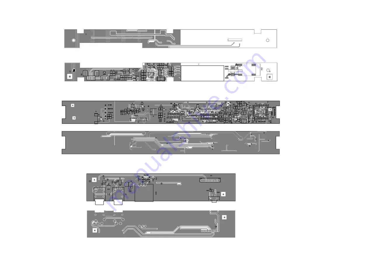
PET1000 IF BOARD DIAGRAM
PET1000 HV POWER BOARD DIAGRAM
9.0 COMPONENT LAYOUT
PET1002 SWITCH BOARD DIAGRAM
Page 1: ...Component Layout 9 Exploded View Diagram Service Part List 10 Revision List 11 Service Manual Technical Specification 1 OSD TEST CONFIGURATION SETUP Copyright 2005 Philips Consumer Electronics B V Eindhoven The Netherlands All rights reserved No part of this publication may by reproduced stored in a retrieval system or transmitted in any form or by any means electronics mechanical photocopying or ...
Page 2: ...tion 32dB typ Left Right Channel Balance 1dB Supported disc type DVD video discs Audio CD DivX video discs In addition this unit can play DVD R DVD RW and CD R CD RW that contains audio titles or MP3 or JPEG files You cannot play disc other than the above listed CVD CD ROM CD Extra CD G and CD I discs cannot be played on this DVD player Software upgrades For the best performance of your DVD Portab...
Page 3: ... caso di non osservazione della più grande cauzione alla loro manipolazione Durante le riparazioni occorre quindi essere collegato allo stesso potenziale che quello della massa dell apparecchio tramite un braccialetto a resistenza Assicurarsi che i componenti e anche gli utensili con quali si lavora siano anche a questo potenziale Pour votre sécurité ces documents doivent être utilisés par des spé...
Page 4: ... operates properly after replacement if it was subject to electrostatic discharge during replacement its life might be shortened When replacing use a conductive mat soldering iron with ground wire etc to protect the laser diode form damage by static electricity And also the LSI and IC are same as above Soldering iron with ground wire or ceramic type Ground conductive wrist strap for body Conductiv...
Page 5: ...xists the fault must be located and corrected Repeat the above test with the DVD VIDEO PLAYER power plug reversed NEVER RETURN A DVD VIDEO PLAYER TO THE CUSTOMER WITHOUT TAKING NECESSARY CORRECTIVE ACTION READING SHOULD NOT EXCEED 0 3V DVD VIDEO PLAYER AC OUTLET AC VOLTMETER Test all exposed metal Voltmeter Hook up for Leakage Current Check 0 15uF 150V AC 1500 10W 5000 per volt or more sensitivity...
Page 6: ... DIGITAL AUDIO OUT Digital Audio output jack S VIDEO OUT S Video output jack COMPONENT VIDEO Component video output jack DC IN 9V Power supply socket 3 0 INSTRUCTIONS FOR USE 1 2 3 4 5 6 10 11 12 13 14 7 8 Up down left right cursor OK Confirms selection Pause playback Press twice to stop playback For previous or next chapters tracks or titles Search backward or search forward Starts resumes playba...
Page 7: ... VCD menu page ANGLE Selects DVD camera angle SUBTITLE Subtitle language selector LANGUAGE Language selector MENU Displays MENU page SETUP Enters SETUP menu Remote Control Up down left right cursor Confirms selection On Screen Display on off INFRA RED PORT BATTERY COMPARTMENT 10 11 12 13 14 Pause playback Press twice to stop playback For previous or next chapters tracks or titles Search backward o...
Page 8: ...river and main board as Fig 3 4 Broken connection of DVD driver and main board Fig 3 4 Remove key board and other parts as Fig 5 Fig 5 5 Remove top cover as Fig 6 Fig 4 Remove DVD driver and main board Fig 6 6 screws 6 Remove IF board and HV board as Fig 7 7 Fig 7 Remove LCD TFT as Fig 8 Remove serew to remove LCD TFT as Fig 8 Fig 8 remove screws remove screws remove screws ...
Page 9: ...will show Region Code 2 for Europe 5 Press key to input preference region code see below table 6 Switch off and re switch on the product Verify Region code change done 7 Region Code Region 1 USA 2 EUROPE 3 ASIA PACIFIC 4 AUSTRALIA NEW ZEALAND LATAM 5 RUSSIA INDIA 6 CHINA REMARKS 1 Password is CONFIDENTIAL 2 Region code is printed on product type plate Due to DVD legislation region codes different ...
Page 10: ...n set to customer yes start set OK Check if the power and play button OK replace connector and switch unit replace MAIN BOARD go to other SYMPTOM no yes yes no replace DVD drive SYMPTOM NO IMAGE OR SOUND COMES OUT FROM THE EXTERNAL OUTPUT start Check operation of the DVD drive Does the DVD drive work yes no Replace the main board or the connector ...
Page 11: ...nnector harness broken Replace broken harness yes Remove the LCD cover and plate of the LCD unit to check the connector of the FL harness Is the connector OK no Repair connector Replace FL inverter or LCD no yes Is the connector broken Replace LCD harness or main board yes Remove the LCD cover and plate of the LCD unit to check the connection of the harness to the LCD unit no Is the connection OK ...
Page 12: ...re the connection of the DVD drive and main board Not OK Pick up lens light up OK Insert a DVD disc and turn on the power What is the reaction of the DVD drive The DVD drive works but the initializing operation of the optical pick up lens does not start the optical pick up lens operates twice or abnormal noise sound Replace DVD drive or main board DVD drive does not work The operation of the DVD p...
Page 13: ...tall a good battery does the LED lights up orange while the AC adapter is connected and does the DVD drive operate OK NOTE For this check use a battery which is not fully charged because the LED does not light when the battery is fully charged Before this check make sure other function work correctly no SYMPTOM NO SOUND COMES FROM THE HEADPHONES start Replace main board yes Insert a good headphone...
Page 14: ...mechanism DRIVER CMD5954 16M FlashROM MX29LV160 64M SDRAM HY57V641620 TC4W53 27MHz AUDIO D A PCM1753 RTD2011 TFT MONITOR AUDIO AMP AZ4558 TC74HC4052AFT LM4863MT HIGH VOLTAGE ASS Y 74HCU04 27MHz VIDEO OUT AUDIO OUT PHONE OUT SPEAKER LOUT SPEAKER ROUT L R L R DRIVER 5V 5V AUDIO 5V 5V 3 3V 1 8V AUDIO 5V TFT POWER 3 3V 5V 2 5V 8 8V 16V 10V COAXIAL OUT DC 9V OSCILLATOR OZ9RR BA7660FS TVP5150AM R G B R ...
Page 15: ...ND V2T V4T V6T V8T V10T A VDD 8 8V GND VCOM U D V13T VGH V14T VGL V12T LCD VDD EDGSL GND STV1 DIO1 CPV OE STV2 DIO2 POL GND GND GND 14 5V GND 16 5V GND 3 3V 3 3V GND SPKL SPKL SPKR SPKR GND GND TFT ON OFF BRIGHT CO TFT HV9V TFT HV9V VCOMS GND 3 3V GND B G R GND MODE2 MODE1 SPOI SPIO SPS CLD NC CLS GND GND TFT 5V TFT 5V 1 2 3 4 5 6 7 8 9 10 11 12 1 2 3 4 5 6 7 8 9 10 11 12 DCIN POWER SW GND Headpho...
Page 16: ... 126 RD9 128 RD10 127 RD8 129 DACVSSC 192 YUV1 Y 191 DACVDDB 190 YUV2 C 189 DACVSSB 188 YUV3 CVBS 187 DACVDDA 186 YUV4 G 185 DACVSSA 184 YUV5 B 183 YUV6 R 182 VSYNC V_ADIN1 181 YUV7 180 HSYNC V_ADIN2 179 DVSS 178 IO_17 177 C0 IO_0 176 C1 IO_1 175 DVDD18 174 C2 IO_2 173 C3 IO_3 172 C4 IO_4 171 DVDD3 170 C5 IO_5 169 C7 IO_7 167 C6 IO_6 168 YUVCLK IO_8 166 Y0 IO_9 165 Y1 IO_10 164 Y2 IO_11 163 Y3 IO_...
Page 17: ... FB3 10 COMP3 11 CDET 12 SW2 17 SW2 18 PGND 19 REG 20 SW1 21 SW1 22 BOOT1 23 PVCC1 24 VCC 25 FIN FIN N6 BA033 IN 1 GND 3 OUT 2 VD101 BA05 IN 1 GND 3 OUT 2 C144 30P VD32 DTA124 C194 2 2U VD001 UPA1716G 1 2 3 4 5 6 7 8 R118 15K C24 16V 10U CB65 100N CB108 100N VD003 B240A CB10 100n R173 51K R7 20K HEC4801 010010 JS001 C091 10U 10V R002 1K C049 100U 16V N102 BQ24103 OUT 1 STAT1 2 IN 3 IN 4 PG 5 VCC 6...
Page 18: ...97 R 98 ADC_VDD 90 ADC_GND1 91 ADC_REFIO 89 ADC_GND0 88 PLL_TEST1 80 PLL_TEST2 81 XO 74 XI 73 DPLL_VDD 78 DPLL_GND 77 APLL1_VDD 79 APLL1_GND 82 APLL2_VDD 84 APLL2_GND 83 APLL3_VDD 85 APLL3_GND 86 PLL_GUARD_VDD 75 PLL_GUARD_GND 76 GNDO 9 GNDO 24 GNDO 37 GNDO 52 GNDO 65 GNDO 102 GNDO 105 VCCO 10 VCCO 23 VCCO 38 VCCO 51 VCCO 66 VCCO 106 VCCO 123 GNDO 124 GNDK 12 GNDK 25 GNDK 53 GNDK 72 GNDK 125 VCCK ...
Page 19: ...IRCUIT DIAGRAM 1 CN1 F1 ENA CT GNDA DIV2 DIV1 VDDA VSEN ISEN IC1 C1 C2 C3 C4 C6 R1 R2 R4 R5 C8 C9 1 CN2 C10 R6 R8 Q3 SOT 23 R10 R11 C11 1 3 2 D2 R9 C7 1210 2 Q1 1 3 2 D1 Q4 SOT 23 S1 1 G1 2 S2 3 G2 4 D2 5 D2 6 D1 7 D1 8 U1 1 2 3 4 5 T1 UI8 5 R3 ...
Page 20: ...PET1000 IF BOARD DIAGRAM PET1000 HV POWER BOARD DIAGRAM 9 0 COMPONENT LAYOUT PET1002 SWITCH BOARD DIAGRAM 9 0 COMPONENT LAYOUT ...
Page 21: ...PET1002 MAIN BOARD DIAGRAM 9 0 COMPONENT LAYOUT ...
Page 22: ...PET1002 PET1008 994000002585 CHROMATISM CABLE CCABLE PET1002 PET1008 994000002586 S VIDEO CABLE SVCABLE PET1002 05 994000003524 ADPV18A AC POWER ADAPTOR 05 ACADAPTOR PET1002 00 PET1008 00 994000003946 AC POWER ADAPTOR 00 ACADAPTOR PET1002 37 994000003947 ADPV26A AC POWER ADAPT0R 37 ACADAPTOR PET1002 93 996500042048 ADPV25A AC POWER ADAPTOR 93 ACADAPTOR PET1002 PET1008 994000003948 CAR CIGARETTE AD...
Page 23: ...PET1002 PET1008 994000002159 PET1000 HV PCB ASS Y 120 PET1002 PET1008 994000003944 PET1002 FUNCTION PCB ASS Y 130 PET1002 PET1008 994000002241 20 PIN HARNESS LE105 142 PET1002 PET1008 994000002584 20 PIN HARNESS LE165 146 PET1002 PET1008 994000003943 PET1002 SWITCH PCB ASS Y 150 PET1002 PET1008 994000002163 PET1000 TFT LCD 200 PET1002 PET1008 994000002228 DV23 LOADING ASS Y 210 ...
Page 24: ...008 994000003949 TOP COVER DISCRETENESS 300 PET1002 PET1008 994000002591 DISPLAY FRAME 310 PET1002 PET1008 994000002589 MIDDLE CABINET 320 PET1002 PET1008 994000003951 BASE COVER 330 PET1002 PET1008 994000002992 KEY DISCRETNESS 350 PET1002 PET1008 994000002166 DOOR DISCRETNESS 360 PET1002 PET1008 994000002593 DOOR SPRING 410 ...
Page 25: ...ption Photos Location Code PET1002 PET1008 996510002088 ON OFF KNOB 420 PET1008 00 314017910141 DTM150 TECHNICAL SET 500 PET1008 00 314107941051 ADAPTOR AC TO DC 9V 1 11A ACADAPTOR PET1008 00 314107941041 ANTENNA CABLE ANTENNA PET1008 00 313923810891 RC19137008 01 REMOTE RC PET1008 00 31410791061 SCART CABLE AY3929 SCABLE ...
Page 26: ...e part 996500039077 ADPV25A ADAPTOR 93 Version 1 2 3141 785 30822 Chapter 10 Revised 12NC of ADPV25A ADAPTOR 93 to 996500042048 Added the location code of all spare parts Version 1 3 3141 785 30823 Chapter 10 Added new spare part for PET1008 Version 1 4 3141 785 30824 Chapter 10 Added new spare part 996510002088 ON OFF POWER KNOB ...
Page 27: ...www s manuals com ...