background image

GC7011 - GC7040

13-18


Due to the high wattage of the iron, only the specified cord set must be used.


Should damage be observed on the 

POWER CORD 23

, it must be replaced. 

Continued usage is not allowed.


If 

STAND BOTTOM 12

 is provided without type plate information eg. Type number, voltage etc.  When replacing the cover, 

engrave the type number & voltage on the type plate with a sharp object.


After the product has been repaired, it should function properly and has to meet the safety requirements & legal regulation 

as laid down & officially established at this moment.


The following tests are common checks that are conducted on a repaired product before it is returned to the consumer.

1. Soleplate 

temperature

Check the soleplate temperature is within IEC requirement.

Soleplate temperature (Deg C)

Materials, for example

Test-
point

==

Minimum

Maximum

120

143

All fabric types

2. Leakage 

current

Check that leakage current is within IEC requirement.

Measure leakage current between LIVE/NEUTRAL & EARTH.

IEC requirement is that at 230 V supply, the EARTH leakage current must be less than 0.75 mA.

3. 

Water leakage / Functionality

Check that there is no water leakage from any part of product during operation.

Check that the functionality of the product (product dependent) eg. Steaming, steam trigger, variable steam, SOS, PCBA 

etc is working properly.

4. Loose 

part

Check that there are no loose parts eg. Extra screws in the product that can cause short-circuit or product malfunctions.

5. 

Fuse open circuit


When replacing fuse, to also service the water tubes which is probably choked with calc.

6. 

PCBAs ESD control

All failed PCBAs including to be packed with ESD bags for shipment.

7. Screws

Screws should be the defi ned screws in terms of length and material used.

8. Self-Check 

mode

8.1.  Introduction of Self-Check mode

Self-Check mode is facilitated by a built-in diagnosis program, which tests and activates all hardware inputs and 

outputs sequentially, with the aid of testing personnel’s interaction and observation.

Self-Check mode is 

NOT

 an exhaustive diagnosis, but a quick preliminary check on all the hardware function.

Further test and troubleshooting may still be required to identify the root cause.

8.2.  Before start Self-Check mode, please do the following checking

1.  Make sure Soleplate is cold (< 100 °C)

2.  Power meter in place to monitor system power

Repair Instruction

Summary of Contents for PerfectCare Viva GC7037

Page 1: ...age compartment Cord storage Cord clip Hose length 1 6m Safe for all fabrics Even for delicate like silks Power cord length 1 8m Sustainability Energy saving 10 energy reduction Calc management Suitable for tap water Calc clean solution Smart Calc Clean Calc clean reminder Safety Information This product meets the requirements regarding interference suppression on radio and TV After the product ha...

Page 2: ...ock Water tank 1700 ml 1700 ml 1700 ml 1700 ml 1700 ml Power cord length 1 8 m IEC 1 8 m IEC 1 8 m IEC 1 8 m IEC 1 8 m IEC Hose length 1 6 m 1 6 m 1 6 m 1 6 m 1 6 m Model Number GC7037 GC7038 GC7039 GC7040 Color Petro Dusk Blue Blue Petro Dusk Power 2400 W 2400 W 2400 W 2400 W Heat up time 2 min 2 min 2 min 2 minw Steam pressure 5 3 bar 5 5 bar 5 5 bar 5 5 bar Continuous Steam 120 g min 120 g min ...

Page 3: ...TRIGGER SPRING SCREW CAP 27 Remove TRIGGER 9 Remove Screw D1 Remove IRON BOTTOM CAP 28 Remove RUBBER CAP 29 Remove DECO PLATE ASSY 11 Remove Screw E1 E2 Remove HOUSING 4 Remove DOSING HEAD 2 COVER RUBBER CAP 30 RUBBER BUNG 31 COVER 3 CHASSIS 8 IRON BOTTOM CAP 28 SOLEPLATE ASSY 1 Remove COVER RUBBER CAP 30 Remove RUBBER BUNG 31 Remove Screws F1 F2 G1 Remove COVER 3 Remove Screw H1 H2 Remove CHASSIS...

Page 4: ... C2 Remove LOCK ASSY 31 Remove Screw D1 D10 Remove HOSE GUIDE 33 Remove STAND BOTTOM CAP 13 Remove STAND BOTTOM 12 Remove WATERTANK ASSY 21 FILLING DOOR 22 POWER BUTTON 24 HOSECORD CLAMP 32 HOSECORD 7 PCBA 25 PUMP ASSY 14 Remove FILLING DOOR 22 Remove Screw E1 E2 Remove POWER BUTTON 24 Remove Screw F1 F2 Remove HOSECORD CLAMP 32 Remove DE AIR TUBE 34 Remove HOSECORD 7 Remove Screw G1 Remove PCBA 2...

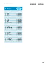
Page 5: ...2 12 Stand bottom 4239 021 86382 4239 021 86382 4239 021 86382 4239 021 86382 13 Stand bottom cap 4239 026 58982 4239 026 58982 4239 026 58982 4239 026 58982 14 Pump Assy 4239 021 83081 4239 021 83081 4239 021 83081 4239 021 83081 15 Tube pump inlet 4239 015 61103 4239 015 61103 4239 015 61103 4239 015 61103 16 Tube pump outlet 4239 015 61092 4239 015 61092 4239 015 61092 4239 015 61092 17 Hose cl...

Page 6: ...bottom 4239 021 86382 4239 021 86382 4239 021 86382 4239 021 86382 13 Stand bottom cap 4239 026 58982 4239 026 58982 4239 026 58982 4239 026 58982 14 Pump Assy 4239 021 83081 4239 021 83081 4239 021 83081 4239 021 83081 15 Tube pump inlet 4239 015 61103 4239 015 61103 4239 015 61103 4239 015 61103 16 Tube pump outlet 4239 015 61092 4239 015 61092 4239 015 61092 4239 015 61092 17 Hose clip 4239 010...

Page 7: ... 021 86382 4239 021 86382 4239 021 86382 4239 021 86382 13 Stand bottom cap 4239 026 58982 4239 026 58982 4239 026 58982 4239 026 58982 14 Pump Assy 4239 021 83081 4239 021 83081 4239 021 83081 4239 021 83081 15 Tube pump inlet 4239 015 61103 4239 015 61103 4239 015 61103 4239 015 61103 16 Tube pump outlet 4239 015 61092 4239 015 61092 4239 015 61092 4239 015 61092 17 Hose clip 4239 010 13341 4239...

Page 8: ...672 11 Deco plate Assy 4239 021 83682 12 Stand bottom 4239 021 86382 13 Stand bottom cap 4239 026 58982 14 Pump Assy 4239 021 83081 15 Tube pump inlet 4239 015 61103 16 Tube pump outlet 4239 015 61092 17 Hose clip 4239 010 13341 18 Tray LE HE 4239 021 95401 19 Tray rubber 4239 015 60431 20 Tray cap 4239 026 59021 21 Water tank Assy 4239 021 83702 22 Filling door 4239 026 59101 23a Power cord EU 24...

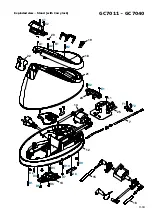
Page 9: ...GC7011 GC7040 9 18 C1 D1 G1 E1 A1 F2 F1 H2 H1 J1 J2 E2 C2 C3 B1 11 1 3 7 5 9 10 2 8 4 6 Exploded view Iron ...

Page 10: ...GC7011 GC7040 10 18 C1 C2 A1 E1 G1 E2 F2 F1 B1 A2 B2 D2 D3 D5 D6 D4 D10 D8 D9 D7 D1 25 7 13 12 15 16 20 22 19 18 21 24 14 Exploded view Stand without Carry lock ...

Page 11: ...GC7011 GC7040 11 18 C1 C2 A1 E1 G1 E2 F2 F1 B1 A2 B2 D2 D3 D5 D6 D4 D10 D8 D9 D7 D1 25 7 13 12 15 16 20 22 19 18 21 24 14 Exploded view Stand with Carry lock ...

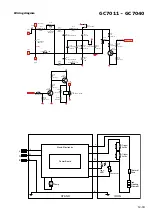
Page 12: ...5W 8005 5V1 0 5W 2001 NOPOP 100nF 275V MKP 10 2004 330µF 10V RE 20 2003 100µF 63V RE 20 2005 330µF 10V RE 20 3005 10k 0805 5 3006 100k 0805 5 3008 0R 1206 3010 100k 0805 5 3009 4k7 1206 5 3007 10k 0805 5 3004 22R MF 5 0 5W 7002 PBSS8110T 7003 BC846B 7004 BC856B 7001 BSS84 3013 47k 1206 5 8006 BAS16 4001 201N 1A H C 24VDC 3014 100k 0805 5 3012 47k 0805 5 3027 1k 0805 5 3011 47k 0805 5 Iron LED STAN...

Page 13: ...mA 3 Water leakage Functionality Check that there is no water leakage from any part of product during operation Check that the functionality of the product product dependent eg Steaming steam trigger variable steam SOS PCBA etc is working properly 4 Loose part Check that there are no loose parts eg Extra screws in the product that can cause short circuit or product malfunctions 5 Fuse open circuit...

Page 14: ...elf Check mode successfully Turn off mains power Unplug in mains cord PowerLED blue turnson YES NO Wait for at least 5 sec Press steam trigger twice within 1 sec before Power LED turns off Entered Self Check mode YES NO If fail to enter Self Check mode could be due to 1 No power to PCBA 2 Buttons malfunction 3 Steam trigger malfunction 4 Timing incorrect Refer to Trouble shooting tip 8 trigger pre...

Page 15: ...sing detection circuit Power LED blue fast blinks Power LED stops blinking and remains on Check iron temperature sensing circuit ECO LED stops blinking and remains on Power LED blue ECO LED green Rinse LED orange scrolling anti clockwise Power LED blue ECO LED green Rinse LED orange fast blink ECO LED green fast blink Turn on Iron heater for 2 sec if iron is cold System activities Iron LED blue fa...

Page 16: ...nt Open Circuit check resistance between Iron Live and Neutral signal Power PCBA problem check by test another board a b c Iron LED does not fast blink when tilt iron fault could be due to 1 Hose cord signal wire broken check wire connectivity Motion sensor failure check by replacing iron PCBA located in iron handle Power PCBA problem check by test another board a b c Hose cord signal wire broken ...

Page 17: ...leaning restrictor Service center to perform pump restrictor cleaning via following step if observe pump not pumping water 1 De assemble water tube of pump 2 Clean restrictor via sharp object 3 Re assemble stand Repair Instruction ...
Page 18: ...icated the non spare part with table in part list page Indicated the non spare part location with numbering in exploded view Corrected the screw labelling in exploded view Highlighted critical component with zoom in picture in exploded view Added in troubleshooting guide Added in Self Check mode Version 2 Created on 25 Mar 2016 Changed Pos 21 in FC7035 20 Added Pos 7 in the exploded view History r...

Reviews: