


Service position C (Supply and Amplifier boards loosen)
Service position D (Mains & AV boards loosen)
Service position E (5DTC Mechanism, SD-5.0SA_CH &
DAC boards loosen)
Caution:
1) In some of the service positions the Mains supply is
exposed, therefore service technicians have to exercise
care to prevent electric shock.
2) The copper pattern on the Mains board should be cov-
ered with non-conductive insulation during fault-finding
on other parts of the set.
3) Insulation sheet (eg. thick paper or cardboard) should be
use during fault-finding to prevent short-circuiting of
copper patterns to metallic surroundings.
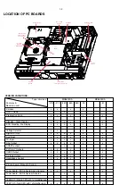
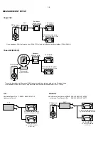
Service positions
2-3
2-3
Thick paper
Thick paper or insulation sheet
should be used to prevent pc boards
copper tracks from short-circuiting
to bottom plate
Mains Board
with non-
conductive
insulation
attached to the
copper pattern
Note:
The ground connection between AV board stoko pin
1100 and Amplifier board stoko pin 1320 must be con-
nect ed during Service pos C and D in order to have
sound output at the Loudspeakers.
Summary of Contents for MX5800SA
Page 68: ...8239 210 93416 3139 113 3494pt6 dd wk0334 PART B 8 13 8 13 SUPPLY BOARD CHIP LAYOUT PART B ...
Page 76: ...3104 213 3525p5 dd wk0334 PART B 8 19 8 19 AMPLIFIER BOARD BOTTOM VIEW PART B ...
Page 78: ...3104 213 3525p5 dd wk0334 PART D 8 21 8 21 AMPLIFIER BOARD TOP VIEW PART D ...
Page 91: ...9 10 9 10 BOTTOM VIEW PART C PART C ...
Page 92: ...9 11 9 11 BOTTOM VIEW PART D PART D 3139 113 3500 pt6 dd wk334 ...
Page 95: ...9 14 9 14 BOTTOM VIEW PART G PART G ...
Page 96: ...9 15 9 15 BOTTOM VIEW PART H PART H 3139 113 3500 pt6 dd wk334 ...
Page 104: ...10 5 10 5 Exploded view 5DTC mechanic for orientation only ...
Page 111: ...BOTTOM VIEW COMPONENT LAYOUT For pcb layout 35037 11 4a 11 4a 3139 113 3503 pt 7 dd wk414 ...
Page 112: ...TOP VIEW PART A 11 5 11 5 PART A ...
Page 113: ...TOP VIEW PART B 11 6 11 6 PART B ...
Page 115: ...TOP VIEW PART B For pcb layout 35037 11 6a 11 6a 3139 113 3503 pt 7 dd wk414 PART B ...
Page 126: ...12 1 12 1 EXPLODED VIEW MAIN UNIT MX5800SA exploded view 3139 119 35170 dd wk318 ...