69
ME5P 15" & 20"
DDC Instructions
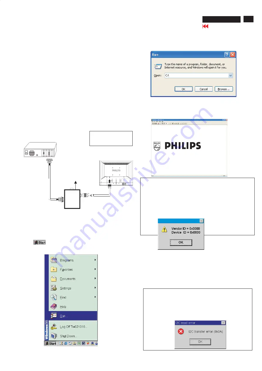
Step 3: Installation of EDID45.EXE
Method 1: Start on DDC program
Start Microsoft Windows.
1. The Program"EDID45.EXE" in service manual cd-rom be copyed to C:\ .
2. Click
, choose Run at start menu of Windows as shown
In Fig. 5.
Fig. 5
4. Click
button. The main menu appears (as shown in Fig. 7).
OK
This is for initialize alignment box.
Fig. 7
Fig. 6
Fig. 8
Note 1: If the connection is improper, you will see the following error
message (as shown in Fig. 8) before entering the main menu.
Meanwhile, the (read EDID) function will be disable. At this
time,
please make sure all cables are connected correctly and
3. At the submenu, type the letter of your computer's hard disk drive
followed by :EDID45 (for example, C:\EDID45, as shown in Fig. 6).
Note 2: During the loading, EDID45 will verify the EDID data which just
loaded from monitor before proceed any further function, once
the data structure of EDID can not be recognized, the following
error message will appear on the screen as below. Please
confirm following steps to avoid this message.
1. The data structure of EDID was incorrect.
2. DDC IC that you are trying to load data is empty.
3. Wrong communication channel has set at configuration setup
1
Configuration and procedure
There are 3 chips contained OSD string, serial number..etc
on the circuit board, main EEPROM which storage all factory settings,OSD
string. DDC IC which storage 128byte EDID data(serial number ..etc.).
Following descirptions are the connection and procedure for Analog
/Digital and main EEPROM can be re-programmed along with
Analog/Digital IC by enable factory memory data write function on the
DDC program (EDID45.EXE).
Initialize alignment box
In order to avoid that monitor entering power saving mode due
to sync will cut off by alignment box, it is necessary to initialize
alignment box before running programming software
(EDID45.EXE). Following steps show you the procedures and
connection.
Step 1: Supply 8-12V DC power source to the Alignment box by
plugging a DC power cord or using batteries.
Step 2: Connecting printer cable and D-Sub cable of monitor as Fig. 4
Fig. 4
PC
1=Power connector
2=D-SUB/DVI connector
To
printer
port
(L
TP1)
DC Power
8-12 V
Fig. 9
Printer
Port
To Monitor
To PC
2
----->
1
----->
Edid45.exe
Edid45.1
Summary of Contents for ME5P
Page 58: ...58 ME5P 15 20 Go to cover page Wiring diagram ...
Page 76: ...Function Block Diagram 76 ME5P 15 20 Go to cover page PANEL ...
Page 77: ...Schematic Diagram of scaler 1 for 15 20 77 ME5P 15 20 Go to cover page ...
Page 78: ...Schematic Diagram of scaler 2 for 15 20 78 ME5P 15 20 Go to cover page ...
Page 79: ...Schematic Diagram of scaler 3 for 15 20 79 ME5P 15 20 Go to cover page ...
Page 80: ...Schematic Diagram of scaler 4 for 15 20 80 ME5P 15 20 Go to cover page ...
Page 81: ...Schematic Diagram of scaler 5 for 15 20 81 ME5P 15 20 Go to cover page ...
Page 82: ...Schematic Diagram of scaler 6 for 15 20 82 ME5P 15 20 Go to cover page ...
Page 83: ...Schematic Diagram of scaler 7 for 15 20 83 ME5P 15 20 Go to cover page ...
Page 84: ...Schematic Diagram of scaler 8 for 15 20 84 ME5P 15 20 Go to cover page ...
Page 85: ...Schematic Diagram of scaler 9 for 15 20 85 ME5P 15 20 Go to cover page ...
Page 86: ...Schematic Diagram of scaler 10 for 15 20 86 ME5P 15 20 Go to cover page ...
Page 87: ...Schematic Diagram of scaler 11 for 15 20 87 ME5P 15 20 Go to cover page ...
Page 88: ...Schematic Diagram of scaler 12 for 15 20 88 ME5P 15 20 Go to cover page ...
Page 89: ...Scaler Board C B A 1 for 15 20 89 ME5P 15 20 Go to cover page ...
Page 90: ...Scaler Board C B A 2 for 15 20 90 ME5P 15 20 Go to cover page ...
Page 91: ...91 ME5P 15 20 Go to cover page YPbPr IN PCB Schematic Diagram For 15 20 ...
Page 92: ...YPbPr IN PCB C B A 1 For 15 20 92 ME5P 15 20 Go to cover page ...
Page 93: ...93 ME5P 15 20 Go to cover page YPbPr IN PCB C B A 2 For 15 20 ...
Page 94: ...KEY PCB Schematic Diagram For 15 20 94 ME5P 15 20 Go to cover page ...
Page 95: ...95 ME5P 15 20 Go to cover page KEY PCB C B A 1 For 15 20 ...
Page 96: ...KEY PCB C B A 2 For 15 20 96 ME5P 15 20 Go to cover page ...
Page 97: ...97 ME5P 15 20 Go to cover page IR LED PCB Schematic Diagram Only for 15 ...
Page 98: ...IR LED PCB C B A 1 Only for 15 98 ME5P 15 20 Go to cover page ...
Page 99: ...99 ME5P 15 20 Go to cover page IR LED PCB C B A 2 Only for 15 ...
Page 100: ...IR LED PCB Schematic Diagram Only for 20 100 ME5P 15 20 Go to cover page ...
Page 101: ...101 ME5P 15 20 Go to cover page IR LED PCB C B A 1 Only for 20 ...
Page 102: ...IR LED PCB C B A 2 Only for 20 102 ME5P 15 20 Go to cover page ...
Page 103: ...103 ME5P 15 20 Go to cover page Power Control Schematic Diagram Only for 15 ...
Page 104: ...Power Control C B A 1 Only for 15 104 ME5P 15 20 Go to cover page ...
Page 105: ...105 ME5P 15 20 Go to cover page Power Control C B A 2 Only for 15 ...