3-1
3-1
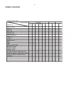
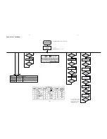
SERVICE TEST PROGRAM
Various
other Tests
Activated with
ACTION
TEST
Disconnect
mains cord
LEAVE SERVICE
TEST PROGRAM
9
to Exit
EEPROM CLEAR
A test pattern will be sent to the EEPROM.
"EEP CLR" is displayed while the erase processing.
Caution! All presets from the customer will be lost!!
Y
N
Y
N
N
PREV
Button pressed?
PREV
Button pressed?
PREV
Button pressed?
DISPLAY
TEST
Display shows Figure 1
All display flags on.
Display shows alternate
segment display from SEG0
to SEG64.
Y
Y
N
9
Button pressed?
No Display shows
Y
N
Y
N
N
DBB
Button pressed?
DBB
Button pressed?
DBB
Button pressed?
ADC
TEST
Display shows "ADC1 Value"
for ADC1
Display shows "ADC2 Value"
for ADC2
Y
Y
N
9
Button pressed?
ADC Test is used for checking the
ADC inputs to the microprocessor.
The display shows an ADC value
between 0 and 255 for an input
signal between 0 and 5V.
Display shows "ADC3 Value"
for ADC3
(Input Line - Door switch status)
Y
Y
N
N
Display shows
Table 1
KEY
TEST
Button pressed?
9
Button pressed?
Display shows the
MCU version
"MCU-Vyy"
(Main menu)
V refers to Version
yy refers to Software version number of the uProcessor
(counting up from 01 to 99)
To enter Service
Testprogram hold
PLAY & Door Open/Close
buttons depressed while
plugging mainscord in.
*
Door switch is ignored
→
CD door can be opened.
(Input Line - Rotary volume)
(Input Line - ioNTC Heat
detection for transformer)
Y
N
DBB
Button pressed?
Display shows "ADC0 Value"
for ADC0
(Input Line - For key scanning)
N
DBB
Button pressed?
Y
Display shows "ADC4 Value"
for ADC4
(Input Line - Version detection)
Figure 1
PROGRAM
NEXT
Key test table
KeyNr
Set key
KeyNr
Set key
KeyNr
Set key
0 CD
10
RDS
20 PROGRAM
1 AUX
11
21 SHUFFLE
2 TUNER
12 CLOCK/DISPLAY
22 NULL
3 SOURCE
13 ALBUM
+
SLEEP
4
STANDBY/ON
14 ALBUM
-
TIMER
5
OPEN/CLOSE
15
SKIP PREV
25
DBB
6
VOLUME DOWN
16 SKIP
NEXT 26 DSC
7 VOLUME
UP
17
NULL
27
MUTE
8 NULL
18
NULL
28
USB
9 NULL
19
REPEAT
23
24
Table 1
Summary of Contents for MCM276R/37
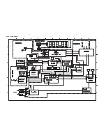
Page 11: ...4 1 4 1 SET BLOCK DIAGRAM ...
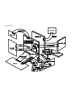
Page 12: ...SET WIRING DIAGRAM 5 1 5 1 ...
Page 18: ...6 6 6 6 LAYOUT DIAGRAM MAIN BOARD 5757 for 37 98 TOP SIDE ...
Page 19: ...6 7 6 7 LAYOUT DIAGRAM MAIN BOARD 5757 for 37 98 BOTTOM SIDE ...
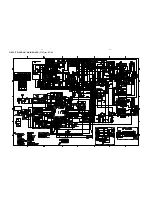
Page 20: ...6 8 6 8 CIRCUIT DIAGRAM MAIN BOARD 5757 for 37 98 ...
Page 23: ...7 2 7 2 LAYOUT DIAGRAM CD MCU BOARD TOP SIDE ...
Page 24: ...7 3 7 3 LAYOUT DIAGRAM CD MCU BOARD BOTTOM SIDE ...
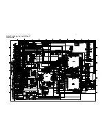
Page 25: ...7 4 7 4 CIRCUIT DIAGRAM CD MCU BOARD CD PORTION ...
Page 26: ...CIRCUIT DIAGRAM CD MCU BOARD MCU PORTION 7 5 7 5 ...
Page 29: ...LAYOUT DIAGRAM AC POWER BOARD TOP SIDE 8 2 8 2 LAYOUT DIAGRAM AC POWER BOARD BOTTOM SIDE ...
Page 30: ...8 3 8 3 CIRCUIT DIAGRAM AC POWER BOARD ...
Page 35: ...9 1 9 1 SET MECHANICAL EXPLODED VIEW 1 ª º 2 4 7 8 9 3 5 6 ...


