2 - 1
AMPLIFIER
Output power .......................................... 2 x 5 W RMS
Signal-to-noise ratio .......................................
≥
65 dBA
Frequency response ............. 100 – 18kHz, ± 3 dB
Input sensitivity AUX ....................... 0.5 V (max. 1 V)
Impedance loudspeakers .....................................
≥
4
Ω
Impedance headphones .................... 32
Ω
-1000
Ω
..................................................................................... <15mW
CD PLAYER
Frequency range ....................................... 100 – 18kHz
Signal-to-noise ratio ............................................ 65 dBA
TUNER
FM wave range ................................... 87.5 – 108 MHz
MW wave range ................................ 531 – 1602 kHz
Number of presets ........................................................ 40
Antenna
FM .................................................................... 75
Ω
wire
MW ......................................................... Loop antenna
SPEAKERS
Bass reflex system
Dimensions (w x h x d) .. 158 x 250x 118 (mm)
GENERAL INFORMATION
AC Power ..................................... 220 – 240 V / 50 Hz
Dimensions (w x h x d, with/without the stand)
............... 211 x 250 x 160/211 x 250 x 126 (mm)
Weight(with/without speakers) ......... 2.9 / 1.23 kg
Standby power consumption ............................ <2 W
Eco power standby ............................................... <1 W
Specifications and external appearance are
subject to change without notice.
USB ................................................................... 12Mb/s, V1.1
......................................... support MP3 and WMA files
Number of albums/ folders ................ maximum 99
Number of tracks/titles ...................... maximum 999
USB PLAYER ( FOR MCM239/MCM239D only )
( MCM238 & MCM239 & MCM239D )
Summary of Contents for MCM239
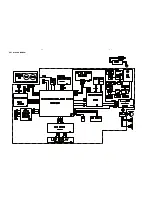
Page 11: ...5 1 5 1 SET BLOCK DIAGRAM ...
Page 12: ...5 2 5 2 SET W IRING DIAGRAM ...
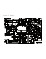
Page 13: ...6 1 6 1 CIRCUIT DIAGRAM C music USB BOARD part1 ...
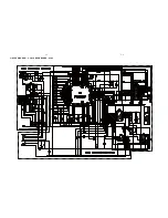
Page 14: ...6 2 6 2 CIRCUIT DIAGRAM C music USB BOARD part2 ...
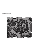
Page 15: ...6 3 6 3 LAYOUT DIAGRAM C music USB BOARD ...
Page 16: ...7 1 7 1 KEY USB JACK BOARD ...
Page 17: ...8 1 8 1 CIRCUIT DIAGRAM POWER AMP JACK BOARD ...
Page 18: ...8 2 8 2 LAYOUT DIAGRAM POWER AMP BOARD ...
Page 19: ...EXPLODE DIAGRAM 9 1 9 1 ...


