3-2
3-2
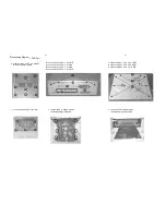
Disassembly Diagram -- AMP Part
B.Loosen 2 PCS 3 X 6 FMTT screws
C.Loosen 2 PCS 3 X 10 BMTT screws
D.Loosen 2 PCS 3 X 10 BTH screws
F. Loosen 1 PCS 3 X 4 FMTT screws
G. Loosen 2 PCS 3 X 6 BMTT screws
H. Loosen 6 PCS 3 X 10 BTH screws
I. Loosen 4 PCS 3 X 6 BM screws
J. Loosen 2 PCS 3 X 4 BMTT screws
K. Loosen 2 PCS 3 X 6 BM screws
L. Loosen 10 PCS 2.6X 8 PA screws
M. Loosen 1 PCS 3 X 10PA screws
A. Loosen screws 9 PCS 3 X 6 BMTT
to remove bottom chassis
B
C
D
F
G
H
I
J
K
L
L
M
L
Summary of Contents for MCD909
Page 9: ...2 2 Malfunction follow check chart ...
Page 15: ...6 2 6 2 Display Board Layout Diagram ...
Page 17: ...7 2 7 2 Prepositive Board Layout Diagram ...
Page 19: ...AMP Board Layout Diagram 8 2 8 2 ...
Page 30: ...Decoder Board Layout Diagram 11 9 11 9 ...
Page 31: ...Explode View DVD Part 12 1 12 1 ...


