


2-3
2-3
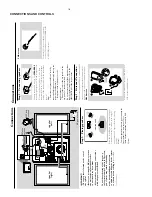
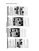
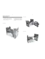
Service position A
Service position B
Service position C
DISMANTLING INSTRUCTIONS
Repair Hints & Service Positions
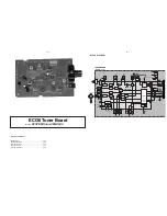
1) During repair it is possible to disconnect the Tuner Board
and/or CD Module completely unless the fault is sus-
pected to be in that area. This will not affect the
performance of the rest of the set.
Note: The flex cables are very fragile, care should be taken
not to damage them during repair. After repair, be
very sure that the flex cables are inserted properly
into the flex sockets before encasing, otherwise faults
may occurs.
Summary of Contents for MCD510/14
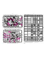
Page 24: ...LAYOUT DIAGRAM DISPLAY BOARD TOP SIDE 6 4 6 4 ...
Page 25: ...6 5 6 5 LAYOUT DIAGRAM DISPLAY BOARD BOTTOM SIDE ...
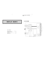
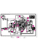
Page 26: ...6 6 6 6 CIRCUIT DIAGRAM DISPLAY BOARD ...
Page 37: ...LAYOUT DIAGRAM MAIN BOARD TOP SIDE 8 2 8 2 ...
Page 38: ...8 3 8 3 LAYOUT DIAGRAM MAIN BOARD BOTTOM SIDE ...
Page 42: ...LAYOUT DIAGRAM CASS BOARD TOP SIDE 9 2 9 2 LAYOUT DIAGRAM CASS BOARD BOTTOM SIDE ...
Page 46: ...10 3 10 3 CIRCUIT DIAGRAM MICROPHONE BOARD ONLY FOR 21M ...


