


1-3
Disc
Laser Type
Semiconductor
Disc Diameter
12cm/8cm
Video Decoding
MPEG-1 / MPEG-2 / DivX
Video DAC
12Bits
Signal System
PAL / NTSC
Video Format
4:3 / 16:9
Video S/N
> 48dB
Audio DAC
24Bits / 96kHz
Total Harmonic
Distortion
<1% (1 kHz)
Frequency
Response
4Hz - 20kHz (44.1kHz)
4Hz - 22kHz (48kHz)
4Hz - 24kHz (96kHz)
S/N Ratio
> 65dBA
General information
AC power
110 - 127V/220 - 240V,
50/60Hz
Dimensions
- Main Unit
(W x H x D)
- Speaker Box
(W x H x D)
173 x 257 x 240mm
173 x 257 x 240mm
Weight
- With Packing
- Main Unit
- Speaker Box
10.8 kg
2.3 kg
2 x 2.8 kg
Ampli
fi
er
Rated Output Power 4X50W RMS
Frequency Response 63 - 14000 Hz, ±3dB
Signal to Noise Ratio > 62dB
Tuner (FM)
Tuning Range
87.5 - 108 MHz
Tuning grid
50 KHz
Sensitivity
- Mono, 26dB S/N Ratio
<22 dBu
Search Selectivity
<28 dBu
Total Harmonic Distortion <3%
Signal to Noise Ratio
> 45 dB
Speakers
Speaker Impedance
6ohm
USB playability information
Compatible USB devices:
USB
fl
ash memory (USB 2.0 or USB1.1)
•
USB
fl
ash players (USB 2.0 or USB1.1)
•
memory cards (requires an additional
•
card reader to work with this apparatus)
Supported formats:
USB or memory
fi
le format FAT12,
•
FAT16, FAT32 (sector size: 512 bytes)
MP3 bit rate (data rate): 32-320 Kbps and
•
variable bit rate
WMA v9 or earlier
•
Directory nesting up to a maximum of 8
•
levels
Number of albums/ folders: maximum 99
•
Number of tracks/titles: maximum 999
•
ID3 tag v2.0 or later
•
File name in Unicode UTF8 (maximum
•
length: 128 bytes)
Unsupported formats:
Empty albums: an empty album is an
•
album that does not contain MP3/WMA
fi
les, and is not be shown in the display.
Unsupported
fi
le formats are skipped. For
•
example, Word documents (.doc) or MP3
fi
les with extension .dlf are ignored and
not played.
AAC, WAV, PCM audio
fi
les
•
DRM protected WMA
fi
les (.wav, .m4a,
•
.m4p, .mp4, .aac)
WMA
fi
les in Lossless format
•
Supported disc formats
Digital Video Discs (DVDs)
•
Video CDs (VCDs)
•
Super Video CDs (SVCDs)
•
Digital Video Discs + Rewritable
•
(DVD+RW)
Compact Discs (CDs)
•
Picture (Kodak, JPEG)
fi
les on CDR(W)
•
DivX® disc on CD-R(W):
•
DivX 3.11, 4.x and 5.x, 6
•
WMA
•
Supported MP3-CD formats:
ISO 9660
•
Max. title/album name: 12 characters
•
Max. title number plus album: 255.
•
Max. nested directory: 8 levels.
•
Max. album number: 32.
•
Max. MP3 track number: 999.
•
Supported sampling frequencies for MP3
•
disc: 32 kHz, 44.1 kHz, 48 kHz.
Supported Bit-rates of MP3 disc are: 32,
•
64, 96, 128, 192, 256 (kbps).
The following formats are not supported:
•
Files like *.VMA, *.AAC, *.DLF,
•
*.M3U,
*.PLS, *.WAV
•
Non-English Album/Title name
•
Discs recorded in Joliet format
•
MP3 Pro and MP3 with ID3 tag
•
SPECIFICATIONS
Summary of Contents for MCD355
Page 2: ...1 2 PCBS LOCATION ...
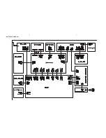
Page 8: ...3 1 3 1 SET BLOCK DIAGRAM ...
Page 9: ...SET WIRING DIAGRAM 4 1 4 1 ...
Page 11: ...5 2 5 2 PCB LAYOUT MAIN BOARD TOP VIEW ...
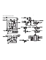
Page 12: ...5 3 5 3 CIRCUIT DIAGRAM MAIN BOARD PART1 ...
Page 13: ...5 4 5 4 CIRCUIT DIAGRAM MAIN BOARD PART2 ...
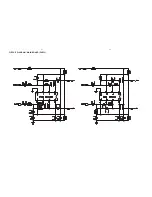
Page 14: ...5 5 5 5 CIRCUIT DIAGRAM MAIN BOARD PART3 ...
Page 15: ...5 6 5 6 CIRCUIT DIAGRAM MAIN BOARD PART4 ...
Page 16: ...5 7 5 7 CIRCUIT DIAGRAM MAIN BOARD PART5 ...
Page 17: ...5 8 5 8 CIRCUIT DIAGRAM MAIN BOARD PART6 ...
Page 18: ...5 9 5 9 CIRCUIT DIAGRAM MAIN BOARD PART7 ...
Page 19: ...5 10 5 10 CIRCUIT DIAGRAM MAIN BOARD PART8 ...
Page 20: ...5 11 5 11 PCB LAYOUT HEADPHONE JACK BOARD CIRCUIT DIAGRAM HEADPHONE JACK BOARD ...
Page 21: ...5 12 5 12 PCB LAYOUT AUX JACK BOARD CIRCUIT DIAGRAM AUX JACK BOARD ...
Page 23: ...6 2 6 2 PCB LAYOUT VFD BOARD TOP VIEW ...
Page 24: ...PCB LAYOUT DISPLAY PANEL BOARD BOTTOM VIEW 6 3 6 3 ...
Page 25: ...6 4 6 4 CIRCUIT DIAGRAM VFD BOARD PART1 ...
Page 26: ...6 5 6 5 CIRCUIT DIAGRAM VFD BOARD PART2 ...
Page 27: ...6 6 6 6 CIRCUIT DIAGRAM VFD BOARD PART3 ...
Page 28: ...6 7 6 7 PCB LAYOUT TOUCH KEY BOARD ...
Page 29: ...6 8 6 8 CIRCUIT DIAGRAM TOUCH KEY BOARD ...
Page 31: ...7 2 7 2 PCB LAYOUT SERVO BOARD TOP VIEW ...
Page 32: ...7 3 7 3 PCB LAYOUT SERVO BOARD BOTTOM VIEW ...
Page 33: ...7 4 7 4 CIRCUIT DIAGRAM SERVO BOARD PART1 ...
Page 34: ...7 5 7 5 CIRCUIT DIAGRAM SERVO BOARD PART2 ...
Page 35: ...7 6 7 6 CIRCUIT DIAGRAM SERVO BOARD PART3 ...
Page 36: ...7 7 7 7 CIRCUIT DIAGRAM SERVO BOARD PART4 ...
Page 37: ...7 8 7 8 CIRCUIT DIAGRAM SERVO BOARD PART5 ...
Page 38: ...7 9 7 9 CIRCUIT DIAGRAM SERVO BOARD PART6 ...
Page 39: ...7 10 7 10 CIRCUIT DIAGRAM SERVO BOARD PART7 ...
Page 40: ...7 11 7 11 CIRCUIT DIAGRAM SERVO BOARD PART8 ...
Page 41: ...7 12 7 12 CIRCUIT DIAGRAM SERVO BOARD PART9 ...
Page 42: ...USB POWER KEY BOARD 8 1 8 1 ...
Page 43: ...8 2 8 2 PCB LAYOUT USB JACK BOARD CIRCUIT DIAGRAM USB JACK BOARD ...
Page 44: ...PCB LAYOUT POWER KEY BOARD 8 3 8 3 CIRCUIT DIAGRAM POWER KEY BOARD ...
Page 45: ...3 7 B 6 D A G 4 2 14 13 C 5 10 11 8 1 9 8 1 8 1 SET MECHANICAL EXPLODED VIEW ...