background image

Items of Safety Attention

1-5

Attention:

Please read <Items of Safty Attention> carefully. If 

there are unexpected conflicts between safefy attention and 
maintenance attention, please abide to safety attention: Safety 
first.

Common Maintenance Attention

Before operating, please unplug the AC power cord from the 
outlet.
a) Disassemble any parts.
b) Cut-off or re-connect plug and other inserting parts.
c) When electrolysis capacitance and test parts is parallel
    connected, anti-polarity and wrong replace will cause
    explosion.
Do not spray chemical on the component system, surroundings 
and any parts.
Clean the electric junction with a cotton stick which is       with 
cleaning mixture, except there is other demand in this manual. 

Please notes:

It is a kind of inflammable mixture.
Do not use lubricant to the soldering point, except there is 
other demand in this manual

Common Controlling

During maintenance, please take common controlling to protect 
component system and electronic parts and prevent damages 
to the circuit due to improper operation.
Led out wire should be kept away from high-pressure or 
high-temperature parts.

ES

Some semi-conductor parts are easily damaged by static 
charges, these parts are called: ES. They are mainly the cores 
of transistor lead identification. The following technical ways 
can be used to reduce the damages by static charges.
Before connecting semi-conductor or the parts. Let off the 
static charges of the body by connection the earth. In the other 
hand, to prevent potential electric shock hazard, please use 
industrial static handle before connecting power for checking 
the equipment.
After unsoldering the ES parts, put the parts on a electric 
surface such as aluminum foil to prevent accumulating static 
charges to damage the parts.
Only use anti-static charges grounded soldering irons to 
unsolder the parts or solder ES parts.
Some soldering tin called “Anti-static charges” can also 
generate charges to damage ES parts.
Do not use poisonous and caustic agent which these kinds of 
chemicals can generate static charges to damage the ES 
parts.
Do not take ES parts out of conductive packages until they are 
used (mostly replacing ES parts is packed with aluminum foil or 
similar conductive materials making a short circuit).
After taking replaceable ES parts from Anti-static charges 
cone, please insert the ES parts in the correctly location soon 
as possible.
During handing sealed ES parts, reduce the movement of the 
body (clothes rubbing and moving on the rug can generate 
static charge to damage the ES parts.)

Maintenance Attention

Common Soldering Rules

Use only grounded low-voltage soldering iron, and proper size and 
shape which can sustain the temperature of soldering horn to 
range from 350 to 390.
Use rosin flux which is demanded by RMA ; include 60%Tin 40% 
lead.
To maintain soldering iron and its tin very well.
Use the wire brush but not spray cleaners such as Freon to clean 
the soldering surface.
Adopt the melting ways:
a) The temperature of soldering horn range from 350 to 390.
b) Heat up the parts pin, until soldering tin is molten.
c) Use the desoldering pump to suck out the molten soldering tin
    quickly.

Note:

 Quickly operating can prevent superheating the 

           electronic-plating copper.
Adopt the following soldering ways.
a) The temperature of soldering horn range from 350 to 390. 
b) Hold the soldering iron and welding rod pointed to the parts pin,
    until soldering tin is molten. Then move the soldering horn      
    quickly to the location that you want to solder. 

Note:

 Quickly operating can prevent superheating 

           electronic-plating copper of printed circuit board.
c) Check the welting zone carefully, then brush the unwanted      
    soldering tin away with a wire brush.

Unsolder/Replace IC

Notes:

Do not touch the IC body directly with soldering iron. 
Pre-heating soldering iron at about 130 for some seconds avoid 
the damages caused by IC heated suddenly. 
For normal IC, the temperature of the solder horn is about 350, 
and can increase to 390 for some bigger IC.
Use the filamentous welding rod and solder which thickness is 
about 0.3mm to solder thin IC and add the solder as needed.
Replace the IC carefully and solder it quickly.
After unsoldering the IC, clean the basic board carefully to ensure 
the board is usable.
Prevent the molten soldering tin dripping on the board which will 
engender a short circuit.
Aim at the first terminal and fix it, then aim at other terminals for 
correctly inserting IC. You can solder quickly just like this.
Before operating, please make sure the IC is unusable. Do not 
unsolder repeatedly. 
During soldering especially soldering a thin IC with many pins, 
check the weld carefully.
After replacing, check that there is not soldering leak, rosin joint, 
short circuit and so on. 

Unsolder:

Use the soldering iron to melt the soldering tin.
Before unsoldering IC, suck out the molten solder tin.

Replace

˖

Make sure all the IC pins are on their correct location, then solder.
Use a wire brush to clean the welting zone.

Summary of Contents for MCD302

Page 1: ...1 7 to 1 8 Software Version Check Upgrade 2 1 Malfuction Check Chart 3 1 Disassembly Diagram 4 1 Block Diagram 5 1 Wiring Diagram 6 1 VFD Display Board 7 Circuit diagram 7 1 Layout diagram 7 2 Decoder Board 8 Circuit diagram 8 1 to 8 6 Layout diagram 8 7 Power Board 9 Circuit diagram 9 1 Layout diagram 9 2 Exploded View 10 1 Service Parts List 11 1 to 11 2 Factory Parts List 12 1 to 12 4 MCD302 5H...

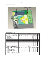
Page 2: ...wer Board Decoder Board VFD Display Board TIPS C Component Lever Repai r M Module Lever Repair Used 55 55 58 58 61 61 79 79 93 93 94 94 96 96 98 98 51 37 12 12 05 05 Feature di ffrence RDS TDS VOLTAGE SELEC TOR ECO S TANDBY DARK M M C Type Versions MCD302 Decoder Board VFD Display Board Power Board 1 1 ...

Page 3: ...DWLR G I 6WHUHR GE 61 5DWLR G I Selectivity G I PDJH 5HMHFWLRQ G 7RWDO DUPRQLF LVWRUWLRQ N 6LJQDO WR 1RLVH 5DWLRQ G 63 56 6SHDNHU PSHGDQFH RKP e 6SHDNHU ULYHU EDVH 6SHDNHU ULYHU WZHHWHU 1 r UHTXHQF 5HVSRQVH GENERAL INFORMATION Total Output power 50W RMS 3RZHU 9 2SHUDWLRQ 3RZHU RQVXPSWLRQ 6WDQGE 3RZHU RQVXPSWLRQ FR 6WDQGE 3RZHU RQVXPSWLRQ HDGSKRQH 2XWSXW 86 LUHFW 9HUVLRQ LPHQVLRQV 0DLQ XQLW Z K G P...

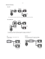
Page 4: ...Hz e g 7122 707 48001 LF Voltmeter e g PM2534 DUT S N and distortion meter e g Sound Technology ST1700B Frame aerial e g 7122 707 89001 Tuner AM MW LW To avoid atmospheric interference all AM measurements have to be carried out in a Faraday s cage Use a bandpass filter or at least a high pass filter with 250Hz to eliminate hum 50Hz 100Hz RF Generator e g PM5326 0 5 i R Bandpass 250Hz 15kHz e g 712...

Page 5: ...rist wrap with resistance Keep components and tools also at this potential ESD CLASS 1 LASER PRODUCT GB Safety regulations require that the set be restored to its original condition and that parts which are identical with those specified be used Safety components are marked by the symbol Philips CE is producing lead free sets from 1 1 2005 onwards Regardless of special logo not always indicated on...

Page 6: ...possible During handing sealed ES parts reduce the movement of the body clothes rubbing and moving on the rug can generate static charge to damage the ES parts Maintenance Attention Common Soldering Rules Use only grounded low voltage soldering iron and proper size and shape which can sustain the temperature of soldering horn to range from 350 to 390 Use rosin flux which is demanded by RMA include...

Page 7: ...RU FXVWRPHU 6 7 2 FKHFN SOD DELOLW 1 SOD DELOLW RN FKHFN SOD DELOLW FKHFN SOD DELOLW UHWXUQ VHW XVWRPHU FRPSODLQW UHODWHG SUREOHP IDVW OHQV FOHDQLQJ RU IODS ORDGHUV DFFHVV WR GULYH SRVVLEOH FOHDQLQJ PHWKRG LV UHFRPPHQGHG FKDQJH 0 RU GHVFULSWLRQ VHH IROORZLQJ SDJHV QVWUXFWLRQ 2Q 3OD DELOLW ...

Page 8: ...UREOHPV UHPDLQ WKH FXVWRPHU LV UHTXHVWHG WR FRQWDFW WKH ZRUNVKRS GLUHFWO 7KH OHQV FOHDQLQJ PHWKRG VKRXOG EH PHQWLRQHG LQ WKH DGGHQGXP VKHHW 7KH ILQDO ZRUGLQJ LQ QDWLRQDO ODQJXDJH DV ZHOO DV WKH SULQWLQJ LV XQGHU UHVSRQVLELOLW RI WKH 5HJLRQDO 6HUYLFH 2UJDQL DWLRQV 48 16 1 1 HFDXVH WKH PDWHULDO RI WKH OHQV LV V QWKHWLF DQG FRDWHG ZLWK D VSHFLDO DQWL UHIOHFWLYLW OD HU FOHDQLQJ PXVW EH GRQH ZLWK D QRQ...

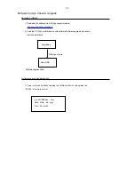
Page 9: ...Software version and date check Ver MCD302 xx Vxxx Date Mmm dd yyyy Time hh mm ss 1 Power on the unit whithout loading the USB and Disc in it then press the 811502 on remote control Upgrading Read USB 2 Load the CD Disc or USB device with software Software upgrade procedure starts automatically Waiting a minute Software upgrade finish ...

Page 10: ...ovided voltage Check if the Transistors have been provided voltage Check the Digital Output Board whether provide voltage Check if the CPU IC has provided voltage Check if the VFD Board has been provided voltage Replace a new Power Board N Replace a new one N Replace a new one N Replace a new one N Replace the IC PT6311 SC16311 CD16311 N N Replace the Main Board N Change to ues the new materials N...

Page 11: ...s screws 3 x 8 BA B1 Loose 5pcs screws 3 x 10 FA B2 Loose 1pc screw 3 x 8 BA A1 Loose 4pcs screws 3 x 8 KA A2 Loose 1pc screw 3 x 10 FA E1 Loose 4pcs screws 3 x 10 BA G1 Loose 4pcs screws 3 x 10 PWA H1 Loose 2pcs screws 2 6 x 10 PA H2 Loose 6pcs screws 2 6 x 8 PA E1 G1 H1 H2 C1 D1 remove this spone H Remove the Display Board G Remove the Loader Driver Mechanism E Remove the Power Board ...

Page 12: ... M5V M5V CVBS DVDL Y Pr S VIDEO Pb Earphone AMP PH LOUT ROUT PT2309 M5V RF SCART CVBS R G B ONLY VER 12 M3 3V M1 8V 5V 27V 27V 5V SWITCHING POWER AC110 220 DVDR COAXIAL AUXR AUXL DVDᴎ㢃 ढ DM 06BXLX L2 DVDᴎ㢃ᬃᶊ 㦅 RT 656n EQ VOL 24C16 AT25FS040 EN25B80 ESMT M12L64164A Switch control TP75S 12V_scart M3 3V M3 3V 9V 12V 1 2 3 4 SPK 4P 25W 25W 4 OHM 4 OHM SM9435A MPEG STB CLK DATA USB VFD DRIVER IR VFD MC...

Page 13: ...6 1 6 1 Wiring Diagram Power Board Decoder Board Display Board DVD Loader Driver ...

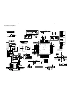
Page 14: ... G2 G3 G4 G5 G6 G7 G8 G9 G10 27V S1 S2 S3 S4 S5 S6 S7 S8 S9 S10 S11 S12 S13 S14 S15 S16 S17 S18 G1 G2 G3 G4 G5 G6 G7 G8 G9 G10 R1031 220 R1032 10 D1012 IN60 DZ1005 3 3V C1021 104 C1020 47U 25V REMOTE X1002 455KHZ R1051 470 R1052 470 R1037 4 7k R1038 4 7k C1028 22P C1029 22P MUTE STANDBY DVD IR MUTE STANDBY GND 5V 5V D1014 4148 27V 1 2 10 9 7 6 3 4 5 B1001 BZ1 L1001 200UH C1013 470 10V R1015 1K R10...

Page 15: ...7 2 7 2 VFD Display Board Layout Diagram ...

Page 16: ...0 1uF CE11 220uF 16V R8 47K L76 0R CB14 0 1uF CE10 220uF 16V R7 2K L98 FB CE3 220uF 16V R11 750 CB10 0 1uF U3 CX1084 3 3V TO 252 3 3 1 2 IN ADJ GND OUT CB4 0 1uF CB13 0 1uF U31 SM9435A 1 2 3 4 5 6 7 8 S S S G D D D D CE8 220uF 16V CB11 0 1uF CE9 100uF 16V L6 FB MK2 C692 2 2uF R12 390 L7 1R MK3 CB16 0 1uF CB152 0 1uF U32 AZ1117H ADJ SOT223 1 3 4 2 ADJ IN OUT2 OUT1 L5 FB 0805 CE118 470uF 10V 8X7 L10...

Page 17: ...24 SMD0 5 TOP 1 2 3 4 5 6 7 8 9 10 11 12 13 14 15 16 17 18 19 20 21 22 23 24 R1058 0 R1072 4 7K Q75 2N3906 2 1 3 L70 FB 600 C17 NC C22 330pF R1053 100K C46 OPEN Q76 8550 DIP 2 1 3 L104 1K 2 7uH CB27 0 1uF R1103 0 J6 CON2 0 11 CON2 0 12 1 2 3 4 5 6 7 8 9 10 11 12 Y3 27MHz R57 0 C13 1uF C44 NC 100pF L11 47uH DIP CB22 0 1uF C21 NC CB148 0 1uF C727 4 7uF R1090 33 R1106 22K Q80 3904 2 1 3 R1065 0 R1059...

Page 18: ...V33 DV33 SD33 SD33 SD33 CB2 NC 0 1uF L106 FB 600 R70 33R CB44 0 1uF CB66 0 1uF R73 10K CE28 100uF 16V RN1 33x4 1 2 3 4 5 6 7 8 CB115 0 1uF R71 10K R1095 10K CE27 47uF 16V CB65 0 1uF U34 ESMT M12L64164A 1 2 4 12 5 7 9 8 10 46 11 13 15 16 17 18 19 35 22 23 24 25 26 14 41 29 30 31 32 33 34 36 37 38 39 40 43 42 44 52 45 47 49 48 50 51 53 54 20 21 3 6 27 28 VCC DQ0 DQ1 VSSQ DQ2 DQ3 VCCQ DQ4 DQ5 VSSQ DQ...

Page 19: ...8 9 10 R104 2 2K R90 0R D85 1N4148 SMD 1 2 R125 75 1 R1100 0R CB57 0 1uF R605 100 L27 FB R98 1K 0805 CB100 0 1uF C33 47pF CE34 10uF 10V R91 0PEN 47K R118 75 1 R100 1K CB63 0 1uF L30 1 8uH SMD R81 0PEN 47K R1104 1K 1W R148 10K CE35 100uF 10V CE43 100uF 16V R117 2 2K Q84 2N3904 2 1 3 C36 47pF CE38 10uF 10V D14 NS EZJZ1V800AA ESD0402 SMD 1 2 L31 1 8uH SMD R80 100K C31 0PEN 100pF R97 10K Q15 2N3906 2 ...

Page 20: ... LIN LOUT BIN_L BOUT_L BIN_R BOUT_R OUT_R OUT_L GND DATA CLK REF C618 470pF CB103 0 12uF CE63 220uF 16V R742 330 C115 1000pF C703 474 50V C612 470pF R982 1K R1111 10K J25 CON2 54 2 1 2 CE82 100uF 16V CE93 10uF 0805 C672 272 CE87 10uF 0805 CE109 10uF 0805 R1112 10K R963 100K CE102 100uF 35V CB85 0 1uF D86 1N4148 1 2 R788 5 6K R1116 4 7K C704 104 CE65 47uF 16V C732 220pF U38 CF4558 5 6 7 8 1 2 3 4 5...

Page 21: ...4 FB 0805 U25 1 2 3 4 5 6 7 8 9 10 11 12 13 14 15 16 17 18 19 20 21 NC FMI RFGND TXO RST SEN SCLK SDIO RCLK VIO VD VDD GND ROUT LOUT DOUT DFS GPO3 DCLK GPO2 IRQ GPO1 NC 21 CE77 100uF 16V C132 22PF L64 120R CB143 0 1uF R333 10K CB139 0 1uF C129 0 47uF CB141 0 1uF CB142 1uF TP5 D46 3 3V SMD C127 100P D42 NC X1 32 768KHz R335 330 R332 10K R326 33 R334 330 R1118 10K R327 FB 1k 100MHz 0603 R331 FB 1k 1...

Page 22: ...8 7 8 7 Decoder Board Layout Diagram ...

Page 23: ... 100K 1 0805 R15 1 5R 5 1206 1 5R 5 1206 1 5R 5 1206 1 0R 5 1206 FQPF8N60 FR104 C4 101 1KV 4 7R 1 2 3 4 4 5 6 7 8 4 3 1 2 2 1 GNDA 3 2 1 C11 471 50V CY3 C9 471 50V 222 250V IC1 PC817 A D8 C14 104 50V 1206 L2 R21 R24 R23 R22 120R 1206 120R 1206 120R 1206 120R 1206 1 0 27 5V CON2 3 96 3P 1 2 10uH C16 T1 C5 102 1KV 102 1KV UF5404 UF5404 R25 1 5K 5 1206 C12 104 50V 0805 CYT431 IC2 10K 5 0805 R20 R18 N...

Page 24: ...9 2 9 2 Power Board Layout Diagram ...

Page 25: ...10 1 10 1 Exploded View ...

Page 26: ...3AAD WXD 8213 LOADER MECHANISM D011 MCD302 USB DOOR SPRING D009 MCD302 FUNCTION BUTTON BRACKET ABS D009 9965 1002 1094 MCM302 12 CD CENTER BUTTON BLACK D010 MCD302 DIRECTION BUTTON ABS BLACK D012 MCD302 USB DOOR ABS D008 9965 1002 8719 MCD302 DISPLAY BOARD VFD USB 75 16 250 5 3 9 U1001 9965 1000 2918 IC PCF8563 AMI8563 SOP8 U1003 9965 1002 3846 IC TM58PC10A ĭ 6 8 1 5 2 9 1 5 2 9 1 5 2 9 D1001 9965...

Page 27: ... DECODER EJS89LA302 93 EJS89L302 D021 9965 1002 9972 POWER BOARD TP75DS 93 TP75DS 5V D008 MCD302 DISPLAY BOARD VFD USB SW1009 9965 2003 3923 TACT SWITCH TC103 6X6X5 170G SW1010 9965 2003 3923 TACT SWITCH TC103 6X6X5 170G SW1011 9965 2003 3923 TACT SWITCH TC103 6X6X5 170G SW1012 9965 2003 3923 TACT SWITCH TC103 6X6X5 170G ...

Page 28: ... H C 2 1 0 1 C 4 3 L L 8 4 1 4 E D O I D P I H C 8 0 0 1 D 4 3 L L 8 4 1 4 E D O I D P I H C 9 0 0 1 D 4 3 L L 8 4 1 4 E D O I D P I H C 0 1 0 1 D 4 3 L L 8 4 1 4 E D O I D P I H C 3 1 0 1 D 4 3 L L 8 4 1 4 E D O I D P I H C 4 1 0 1 D 5 0 8 0 J W 6 1 1 K 0 1 R O T S I S E R P I H C 7 2 0 1 R 5 0 8 0 J W 6 1 1 K 0 1 R O T S I S E R P I H C 8 2 0 1 R 5 0 8 0 J W 6 1 1 K 0 1 R O T S I S E R P I H C 9...

Page 29: ... 1 S T H C T I W S T C A T 1 0 0 1 W S G 0 7 1 5 X 6 X 6 1 0 7 0 3 1 S T H C T I W S T C A T 2 0 0 1 W S G 0 7 1 5 X 6 X 6 1 0 7 0 3 1 S T H C T I W S T C A T 3 0 0 1 W S G 0 7 1 5 X 6 X 6 1 0 7 0 3 1 S T H C T I W S T C A T 4 0 0 1 W S G 0 7 1 5 X 6 X 6 1 0 7 0 3 1 S T H C T I W S T C A T 5 0 0 1 W S G 0 7 1 5 X 6 X 6 1 0 7 0 3 1 S T H C T I W S T C A T 6 0 0 1 W S G 0 7 1 5 X 6 X 6 1 0 7 0 3 1 S...

Page 30: ...ĭ12X1 5 BLACK WHITE SPONGE 47X10X2 40 SCREW 3 X 10 FA BLACK SCREW 3 X 10 BA PLATING SCREW 3 X 5 BMTT PLATING SCREW 3 X 8 BA PLATING SCREW 3 X 8 BA PLATING SCREW 3 X 10 PWA PLATING SCREW 2 6 X 8 PA PLATING SCREW 2 6 X 10 PA PLATING SCREW 3 X 8 KA BLACK SCREW 3 X 10 FA BLACK SCREW 3 X 6 PWTTĭ8W PLATING 28WIRE 150 2 0 12PX1 2 0 12PX1 26SHIELDINGING 220 2 0 4PX1 2 0 4PX1 26SHIELDINGING 180 2 0 4PX1 2 ...

Page 31: ...302 93 QUICK START GUIDE PH WARRANTY CARD V93 120g 2P 3C V1 1 PLASTIC BAG PE 29X18cm PHILIPS K C A J Y C N E U Q E R F H G I H m 5 1 E N I L G N O M 1 C C A ACC2 POWER CORD 1 8m CCC APPROVAL W O L L E Y K C A J A C R m 5 1 E L B A C L A I X A O C 3 C C A 0 0 5 L E R I W Y C N E U G E R F O I D U A 5 3 C D 5 3 C D 4 C C A PLASTIC BAG PE 25X10cm PHILIPS MCD302 93 PACKING PARTS MCD302 PAPER PULP PASS...

Reviews: