background image

1-11

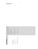
Troubleshooting

The r

emote contr

ol does not function.

The displa

y is dark.

Lo

w hum or buzz sound.

Lo

w bass response.

Unable to select Pr

og

ressiv

e Scan

Select the cor

rect source (DISC or 

TUNER,

 f

o

r

example) bef

ore pressing the function b

utton.

Point the remote control at the remote sensor

of the unit.

Reduce the distance to the pla

ye

r.

Remo

ve

 an

y possib

le obstacles.

Replace the batter

ies with new ones.

Check that the batter

ies are loaded cor

rectl

y.

Press DIM again.

Place the D

VD micro system as far a

wa

y as

possib

le from electr

ical devices that ma

y be

causing interf

erence

.

Check all speak

er

s for cor

rect polar

ity

.

Check that the output of the video signal is

switched to  'Ypbpr'.

Tr

oub

leshooting

Summary of Contents for MCD300

Page 1: ...oard ECO6 01 7 AMP Board 8 Output Terminal Board 9 Circle AMP Board for MCD305 10 Circle Output Board for MCD305 10 Power Board for MCD305 11 Set Mechanical Exploded view parts list 12 Revision List 13 Copyright 2005 Philips Consumer Electronics B V Eindhoven The Netherlands All rights reserved No part of this publication may be reproduced stored in a retrieval system or transmitted in any form or...

Page 2: ...kHz 10 THD Frequency response within 0 5 1 0dB 100Hz 15kHz S Bass Loudness On Off Input sensitivity Aux in at 1kHz 500mV at 600 Ω Output sensitivity Headphone output at 32 kΩ 12mW 1dB Max vol COMPACT DISC Frequency response within 3dB 20Hz 20kHz Output level in Vrms 500mV Zout 100Ω Signal Noise ratio A weighted 65dBA Distortion at 1kHz 0 02 Channel unbalance at 1kHz 2dB Channel separation at 1kHz ...

Page 3: ...15kHz e g 7122 707 48001 LF Voltmeter e g PM2534 DUT S N and distortion meter e g Sound Technology ST1700B Frame aerial e g 7122 707 89001 Tuner AM MW LW To avoid atmospheric interference all AM measurements have to be carried out in a Faraday s cage Use a bandpass filter or at least a high pass filter with 250Hz to eliminate hum 50Hz 100Hz RF Generator e g PM5326 Ri 50Ω Bandpass 250Hz 15kHz e g 7...

Page 4: ...t Disc 4822 395 10216 ESD Equipment Anti static table mat large 1200x650x1 25mm 4822 466 10953 anti static table mat small 600x650x1 25mm 4822 466 10958 Anti static wristband 4822 395 10223 Connectorbox 1MΩ 4822 395 11307 Extension cable to connect wristband to conn box 4822 320 11305 Connecting cable to connect table mat to conn box 4822 320 11306 Earth cable to Connect product to mat or box 4822...

Page 5: ...n osservazione della più grande cauzione alla loro manipolazione Durante le riparazioni occorre quindi essere collegato allo stesso potenziale che quello della massa dell apparecchio tramite un braccialetto a resistenza Assicurarsi che i componenti e anche gli utensili con quali si lavora siano anche a questo potenziale Pour votre sécurité ces documents doivent être utilisés par des spécia listes ...

Page 6: ...es has to be purchased at external companies Special information for BGA ICs always use the 12nc recognizable soldering temperature profile of the specific BGA for de soldering always use the lead free temperature profile in case of doubt lead free BGA ICs will be delivered in so called dry packaging sealed pack including a silica gel pack to protect the IC against moisture After opening dependent...

Page 7: ...nputs a track title chapter number of the disc 4 PROG DVD VCD CD enters the program menu MP3 WMA CD adds deletes a programmed track to from the program list Picture CD during playback to select a slide show mode Tuner programs preset radio stations 5 GOTO ST Disc fast searches in a disc by entering a time title chapter or track FM sets stereo or mono sound mode 6 SYSTEM disc mode only enters or ex...

Page 8: ...SS Virtual Surround Sound or stereo sound effect º VOL SEL unavailable for this version selects different speaker modes DSC selects different types of preset sound equalizer settings CLASSIC JAZZ POP or ROCK LOUDNESS enables or disables automatic loudness adjustment Connections IMPORTANT The type plate is located at the rear of the system Before connecting the AC power cord to the wall outlet ensu...

Page 9: ...tup Note To avoid magnetic interference do not position the front speakers too close to your TV Connecting the power cord After everything is connected properly plug in the AC power cord to the power outlet Never make or change any connection with the power switched on 1 2 Option 1 Option 2 TV Connections Connecting additional equipment IMPORTANT Some discs are copy protected You cannot record the...

Page 10: ...t may be causing the noise Increase the distance between the system and your TV or other equipment Troubleshooting 2 2 WARNING Under no circumstances should you try to repair the system yourself as this will invalidate the warranty Do not open the system as there is a risk of electric shock If a fault occurs first check the points listed below before taking the system for repair If you are unable ...

Page 11: ...int the remote control at the remote sensor of the unit Reduce the distance to the player Remove any possible obstacles Replace the batteries with new ones Check that the batteries are loaded correctly Press DIM again Place the DVD micro system as far away as possible from electrical devices that may be causing interference Check all speakers for correct polarity Check that the output of the video...

Page 12: ...I remove screws M3x8 1pcs J remove screws M2x8 9pcs F Remove Power PCB Board Screws F remove screws M3x8 4pcs G Remove DVD Decoder Card Assy G remove screws M3x7 6 3pcs H Remove VFD board assy H remove screws M2x8 8pcs B Remove Bottom Screws B1 remove screws K2 9x5 25 5pcs B2 remove screws T3x8 3pcs D2 K2 9x5 25 2pcs B3 remove screws M3x8 2pcs C Remove DVD Lader Screws remove screws TP 3x11 4pcs D...

Page 13: ...3 1 3 1 SERVICE TEST PROGRAM ...

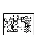
Page 14: ...TRANSFORMER SELENIUM SELENIUM FILTER FILTER AMP DVD R L POWER CONTROL SWITCH 7812 AMC2576 7805 DVD POWER SWITCH CONTROL DVD5V REM SENSO R CONTROL2 KEY CONTROL MUTE CPU 5V 12V V V CPU 5V VF1 2 28V 28V VF1 VF1 VF1 VF2 28V AUX IN TUNERIN DVD IN REM MUTE STANDBY DVD ON OFF L R SCL SDA V TUNER TUNER POWER CONTROL V TUNER 12V CPU 5V ENCORDER ROT A ROT B AM P MUTE VIDEO S VIDEO DVD SW lowpass SET BLOCK D...

Page 15: ...SET WIRING DIAGRAM ONLY FOR MCD300 5 1 5 1 ...

Page 16: ...SET WIRING DIAGRAM ONLY FOR MCD305 5 2 5 2 ...

Page 17: ... G 9 G S1 G 10 G 11 S2 S11 S9 S8 G 8 S3 S4 S13 S14 S15 S16 G 1 G 2 G 3 G 4 G 5 G 9 S17 S10 G 6 G 7 S12 1 2 8 D 8 4 1 4 1 2 0 1 D 8 4 1 4 1 Y E K 2 Y E K 3 Y E K 1 2 R K 3 3 0 2 R K 3 3 9 1 R K 3 3 4 Y E K 8 1 R K 3 3 1 Y E K 2 Y E K 3 Y E K 0 _ 2 S 0 _ 1 S 5 G 0 1 G 9 1 C 4 3 3 8 1 C 4 3 3 4 Y E K S5 S6 S7 3 C 4 0 1 R G V 5 N C P 3 0 2 6 1 R 7 4 0 2 C F u 7 4 5 C 4 0 1 B 2 A 3 G 1 4 5 1 T O R m c ...

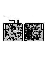
Page 18: ...LAYOUT DIAGRAM CPU BAORD 6 2 6 2 ...

Page 19: ...29 820 R28 820 C40 153 C39 153 1 3 2 CF1 10 7M 1 3 2 CF2 10 7M R1 20K 1 2 3 4 6 T3 11845 20591 1 2 3 4 6 T2 11845 20591 1 2 3 4 6 T1 11844 44023 1 2 3 4 6 T5 44108 C2 104 C1 10uF 1 2 3 4 6 T7 511B E 43462 3 2 1 6 4 5 T4 A9452 20382 R8 5 6K C13 331 C3 47pF R20 22k R26 47 C36 22pF C38 2p2 C37 561 R10 220 D2 BAS316 C11 33pF CV 2 10P C21 1uF R36 33K Q4 BC857C C12 33pF R19 22K R13 1K C20 222 MP X MP X ...

Page 20: ...LAYOUT DIAGRAM TUNER BOARD ECO6 01 7 2 7 2 ...

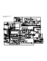
Page 21: ...CIRCUIT DIAGRAM AMPLIFIER BOARD ONLY FOR MCD300 8 1 2 1 8 1 ...

Page 22: ...V E E V 2 0 5 Q 2 7 7 9 2 5 R K 1 2 0 5 R K 7 4 3 0 5 Q 0 5 0 8 3 0 5 R K 7 4 2 3 5 C V 5 3 F u 7 4 3 0 5 C V 6 1 F u 0 2 2 D N G A V 5 6 1 V 5 6 1 8 2 5 R K 7 4 9 0 5 C V 5 2 F u 2 2 O U T 3 G N D 2 I N 1 1 0 5 U 2 1 8 7 D N G D L C S N O D V D C 572 104 M C 571 104 M 7 7 5 R 5 0 7 4 6 7 5 R 5 0 7 4 Y B D N A T S N O T A D S E T U M 1 0 6 2 7 3 C T J H u 2 L 8 0 5 L 1 0 6 2 7 3 C T J H u 2 L 7 0 ...

Page 23: ...LAYOUT DIAGRAM AMPLIFIER BOARD ONLY FOR MCD300 8 3 8 3 ...

Page 24: ...LAYOUT DIAGRAM AMPLIFIER BOARD ONLY FOR MCD305 8 4 8 4 ...

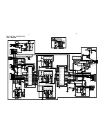
Page 25: ... 3 0 H R J 1 2 3 4 5 6 7 8 9 0 1 1 1 1 0 2 N C P 1 1 0 2 D N G D F I D P S C S Y S S B V C D N G D 4 0 2 L 0 6 3 0 H R J 5 0 2 L 0 6 3 0 H R J 6 0 2 L 0 6 3 0 H R J D E R N E E R G E U L B D N G D 3 2 1 6 5 4 2 0 2 J P 4 A C R G B R LAYOUT DIAGRAM OUTPUT TERMINAL BOARD ONLY FOR MCD300 CIRCUIT DIAGRAM OUTPUT TERMINAL BOARD ONLY FOR MCD305 9 1 9 1 ...

Page 26: ...CIRCUIT A ND LAYOUT DIAGRAM CIRCLE AMP BOARD ONLY FOR MCD305 CIRCUIT A ND LAYOUT DIAGRAM CIRCLE OUTPUT BOARD ONLY FOR MCD305 10 1 10 1 ...

Page 27: ... F V 2 F V V 0 _ 2 1 F V D N G D V 1 2 V 1 2 1 0 4 F V 0 5 2 L A 2 F 2 0 4 D Z 7 V 4 6 0 4 D 1 0 0 4 5 0 4 D 1 0 0 4 V 0 1 2 1 4 R 5 2 0 7 4 0 5 2 0 7 4 0 1 1 4 R 3 1 4 C V 0 5 F u 0 0 1 5 0 4 R K 0 1 5 0 2 2 5 1 4 R 5 0 2 2 4 1 4 R D N G D D N G D V 5 1 F V 2 F V V 8 2 N O D V D V 5 D N G D 1 F V 2 F V V 8 2 C C V 6 1 4 R K 7 4 4 0 4 C 4 0 1 4 1 4 C V 5 3 F u 0 7 4 3 0 4 D 1 0 0 4 4 0 4 D 1 0 0 4...

Page 28: ... EXPLODED VIEW DIAGRAM 12 1 12 1 ...

Page 29: ... BOX ASS Y D300 06 994000003751 FUNCTION KNOB R 994000003737 2P SPEAKER TERMINAL BOARD 07 994000003749 FUNCTION KNOB L 994000003738 SPK GRILLE WD 13 08 994000003731 MINI FAN DC12V 0 07A 994000003753 REMOTE BATTERY COVER 09 994000003744 CABINET BACK D300 994000003817 SPEAKER BOX ASS Y D305 09 994000003827 CABINET BACK D305 994000003818 WOOFER L S ASS Y D305 11 994000003743 CABINET TOP 994000003819 ...

Page 30: ...H SWITCH SW6 994000002555 LIGHT TOUCH SWITCH SW7 994000002555 LIGHT TOUCH SWITCH SW8 994000002555 LIGHT TOUCH SWITCH SW9 994000002555 LIGHT TOUCH SWITCH U1 994000002547 IC AT24C02 PC27 2 7V D300 U1 994000003804 IC AT24C01 AT24C02 2 7V D305 U2 994000003162 CPU U252 OR 3P9228 D300 U2 994000003805 CPU 3S9228 D305 U3 994000002539 IC PT6311 SC16311 CD16311 VFD1 994000003715 VFD DISPLAY NE 300D 1 WR X1 ...

Page 31: ... TEA5757H JACK1 994000003435 ANT TERMINAL L1 994000003833 WOUND COIL 3 5 6 5 0 5mm L2 994000003831 WOUND COIL 3 5 4 5 0 5m L3 994000003832 WOUND COIL 3 5 5 5 0 5mm Q1 994000003156 CHIP TRANSISTOR 9014 Q2 994000003156 CHIP TRANSISTOR 9014 RV1 994000003757 SEMI FIXED RESISTOR 100KR T1 994000003446 I F T COIL 44023 BLACK T2 994000003447 I F T COIL 20591 YELLOW T3 994000003447 I F T COIL 20591 YELLOW ...

Page 32: ... TRANSISTOR 8050 D111 994000003723 TRANSISTOR 8050 F101 994000002531 FUSE F4AL250V F102 994000002531 FUSE F4AL250V F103 994000002529 FUSE F2AL250V FAN 994000003731 MINI FAN DC12V 0 07A J101 994000003728 4P SPK TERMINAL CLIP J102 994000003726 HEADPHONE JACK J105 994000003727 2P RCA SOCKET AV2 8 4 7A J106 994000002558 SINGLE RCA SOCKET L102 994000003717 FIXED INDUCTOR 22uH L104 994000003729 CHOKE CO...

Page 33: ...IC LM7805 LM340T5 7805 U103 994000003157 IC 2576 ADJPB U104 994000003724 IC PT2313L U105 994000002523 IC TDA7264 U106 994000003427 IC NE008 U107 994000002524 IC PT2309 S L ZD102 994000003722 ZENER DIODE 4 7V L 52MM ZD104 994000002516 ZENER DIODE 5V1 L 52mm Note Only these parts mentioned in the list are normal service parts ELECTRICAL PARTSLIST AMP BOARD ONLY FOR MCD300 ...

Page 34: ...1 2µH L510 994000003729 CHOKE COIL JTC3726 01 2µH Q501 994000002519 TRANSISTOR 8550C L 5 0MM Q502 994000002517 TRANSISTOR 2SB772 Q503 994000002518 TRANSISTOR 8050C Q504 994000002518 TRANSISTOR 8050C L 5 0MM Q506 994000003723 TRANSISTOR 8050 Q507 994000003723 TRANSISTOR 8050 Q508 994000002519 TRANSISTOR 8550C L 5 0MM Q509 994000003723 TRANSISTOR 8050 Q510 994000003723 TRANSISTOR 8050 U501 994000002...

Page 35: ...TEREO POWER IC U704 994000002526 IC 7812 Note Only these parts mentioned in the list are normal service parts POWER BOARD ONLY FOR MCD305 D401 994000002521 THYRISTOR RS406 4A F401 994000002529 FUSE F2AL250V L402 994000003717 FIXED INDUCTOR 22uH Q402 994000002518 TRANSISTOR 8050C L 5 0MM U401 994000002548 IC LM7805 LM340T5 7805 U402 994000003157 IC 2576 ADJPB TO 220B CIRCLE OUTPUT BOARD ONLY FOR MC...

Page 36: ...5 FLAT FLEX CABLE 200mm D300 994000003756 FLAT FLEX CABLE 220mm D300 994000003821 SWITCH RS 1209 D305 994000003823 DC FAN 12V 0 12A D305 994000003829 24P FFC 150mm D305 994000003828 FLAT FLEX CABLE 26 D305 994000003814 TOROIDAL TRASFO 220V 50Hz D305 994000003834 DVD DECODER BOARD D305 Note Only these parts mentioned in the list are normal service parts 12 9 ...

Page 37: ...LIST 1 0 Manual 3141 785 30650 Initial Service Manual released 1 1 Manual 3141 785 30651 In this version the electrical partslist are updated P12 8 Item J801 Code Number changed from 9940 000 03825 to 9940 000 03813 ...

Reviews: