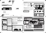
5-1
5-1
DISASSEMBLY
DIAGRAM
Dismantling
of
the
Rear
Cabinet
Dismantling
of
the
PCB
Board
1
)
Remove
6
screws
E
as
indicated
to
loosen
the
Main
Board
.
3
)
Remove
2
screws
G
as
indicated
to
loosen
the
Key
Board
.
2
)
Remove
4
screws
F
as
indicated
to
loosen
the
Display
Board
.
4
)
Remove
4
screws
H
as
indicated
to
loosen
the
USB
jack
Board
.
3
)
Remove
a
rubber
foot at
bottom
of
the
unit
as
indicated
.
2
)
Remove
4
screws
B
and
4
screws
C
as
indicated
.
4
)
Remove
2
screws
D
as
indicated
to
loosen
the
Rear
Cabinet
.
1
)
Remove
8
screws
A
as
indicated
to
loosen
the
speaker
cabinet
.
RIGHT
SPEAKER
CAB
.
LEFT
SPEAKER
CAB
.
B
A
C
D
D
E
F
G
H
REAR
CABINET
Summary of Contents for MCD263
Page 10: ...CIRCUIT DIAGRAM MAIN BOARD POWER AMP SECTION 6 1 6 1 ...
Page 11: ...CIRCUIT DIAGRAM MAIN BOARD EQ TUNER SECTION 6 2 6 2 ...
Page 12: ...CIRCUIT DIAGRAM MAIN BOARD DVD SECTION 6 3 6 3 ...
Page 13: ...CIRCUIT DIAGRAM MAIN BOARD DVD SECTION 6 4 6 4 ...
Page 14: ...CIRCUIT DIAGRAM MAIN BOARD DVD SECTION 6 5 6 5 ...
Page 15: ...CIRCUIT DIAGRAM MAIN BOARD DVD SECTION 6 6 6 6 ...
Page 16: ...LAYOUT DIAGRAM MAIN BOARD 6 7 6 7 ...
Page 17: ...CIRCUIT DIAGRAM DISPLAY MCU KEY BOARD 7 1 7 1 ...
Page 18: ...LAYOUT DIAGRAM DISPLAY MCU BOARD TOP SIDE 7 2 7 2 ...
Page 19: ...LAYOUT DIAGRAM DISPLAY MCU BOARD BOTTOM SIDE 7 3 7 3 ...
Page 20: ...LAYOUT DIAGRAM KEY BOARD 7 4 7 4 ...
Page 21: ...CIRCUIT DIAGRAM USB HP JACK BOARD 8 1 8 1 ...
Page 22: ...LAYOUT DIAGRAM USB HP JACK BOARD 8 2 8 2 ...
Page 23: ...SET EXPLODED VIEW 9 1 9 1 ...


