3 - 2
CONNECTION AND CONTROLS
Using an accessor
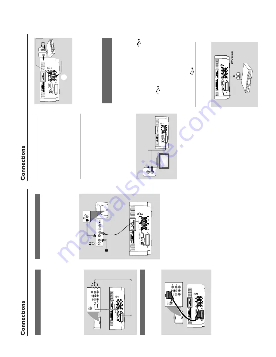
y RF modulator
IMPOR
T
ANT!
–
If y
our
TV set only has a single
Antenna In jack (or labelled as 75 ohm or
RF In),
y
ou will need a RF modulator in
or
der to vie
w the D
VD pla
yback via
TV
.
See y
our electr
onics r
etailer or contact
Philips f
or details on RF modulator
a
vailability and operations.
1
Use the composite cab
le (y
ello
w) to connect the
system's
VIDEO
jack to the video input jack on
the RF modulator
.
2
Use an RF coaxial cab
le (not supplied) to
connect the RF modulator to y
our
TV's RF jack.
Using component
Video In jack (Pr Pb
Y)
●
Use the component video cab
les (red/b
lue/
green,
not supplied) to connect the system’
s
PR/
PB/ Y
jacks to the cor
responding Component
video input jacks (or labeled as Pr/Cr Pb/Cb
Y or
YUV) on the
TV set.
●
To
listen to
TV channels through this system,
use
the audio cab
les (white/red) to connect
AUX
IN (L/R)
jacks to the cor
responding
A
UDIO
OUT jacks on the
TV set.
1
.000
Using Scar
t jack
1
Use the scar
t cab
le (not supplied) to connect
the system’
s
TV SCAR
T OUT
jack to the
corresponding SC
AR
T input jacks on the
TV set.
1.000
TO
TV
TO
TV
2
To
listen to
TV channels through this system,
use
the scar
t cab
le (not supplied) to connect the
system’
s
TV SCAR
T OUT
jack to the
corresponding SC
AR
T output jack on the
TV set.
●
Bef
ore star
ting oper
ation,
press
AUX
on th
e
remote control to select
“TV”
in order to
activate the input source
. The m
usic will be heard
through the speak
er
s.
1.000
AUDIO IN
R L
VIDEO
IN
TO TV
ANT IN
CH3 CH4
RF coaxial cable to
TV
Back of RF Modulator
(example only)
Antenna or
Cable TV
signal
Step
5:
Connecting the po
w
e
r
cor
d
IMPOR
T
ANT!
–N
ev
er mak
e or chang
e an
y connection
with the po
w
er s
witched on.
the
A
C
po
w
er cord to the system and then to
the po
w
er outlet.
Optional:
Connecting additional
equipment
IMPOR
T
ANT!
–
Some discs are cop
y-pr
otected.
Y
o
u
cannot r
ecor
d the disc thr
ough a
VCR or
digital r
ecor
ding de
vice
.
–W
hen making connections,
mak
e
sur
e
the colour of cab
les matches the colour
of jacks.
–A
lwa
ys r
e
fer to the o
wner's man
ual of
the other equipment f
or complete
connection and usa
g
e
details.
1
.000
A
UDIO OUT
L
R
A
Listening to the pla
yback of other
equipment
A
Use a cinch cab
le (not supplied) to connect
A
UX on the rear panel of the D
VD pla
yer to the
analogue audio out terminals of an exter
nal
equipment (TV
, VCR,
Laser Disc pla
ye
r, D
V
D
pla
yer or CD Recorder).
Bef
ore star
ting oper
ation,
press
SOURCE
on
the front panel to select
A
UX or press
AUX
on
the remote in order to activate the input source
.
Note:
–
If you ar
e connecting equipment with a mono
output (a single audio out terminal), connect it to
the
AUX left terminal.
Alternatively
, you can use a
“single to double”
cinch cable (the output sound
still r
emain mono).
1
.000
A
UDIO IN
L
R
VIDEO IN
L
B
Using the
VCR f
or r
ecor
ding D
VDs
B
Connect one of the system's
VIDEO OUT
jacks to the cor
responding
VIDEO IN jack and
LINE OUT (R/L)
jacks to the
A
UDIO IN jacks
on the
VCR.
This will allo
w y
ou to mak
e analogue
stereo (tw
o channel,
r
ight and left) recordings.
Connecting a USB de
vice or memor
y
car
d
By connecting a USB mass stor
age device
(including USB flash memor
y, USB flash pla
ye
rs
or memor
y cards) to the system,
y
ou can enjo
y
the device's stored m
usic through the po
w
erful
speak
er
s of the system.
●
Inser
t the USB device's USB plug into the
sock
et on the set.
for the de
vices with USB cab
les:
1
Inser
t one plug of the USB cable (not supplied)
to the
sock
et on the set.
2
Inser
t the other plug of the USB cab
le to the
USB output ter
minal of the USB device
.
for the memor
y car
d:
1
Inser
t the memor
y card into a card reader (not
supplied).
2
Use a USB cab
le (not supplied) to connect the
card reader into the
sock
et on the set
.
Step 6:
Connecting digital
audio equipment
1
.000
D
igital audio
re
c
o
rd
e
r
Summary of Contents for MCD149
Page 9: ...3 3 CONNECTION AND CONTROLS Controls Controls 7 1 2 3 4 5 6 8 9 0 1 7 8 6 4 0 7 8 5 2 3 9 2 ...
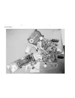
Page 13: ...5 2 5 2 WIRING DIAGRAM ...
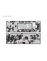
Page 15: ...LAYOUT DIAGRAM DISPLAY BOARD 6 2 6 2 ...
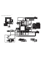
Page 16: ...7 1 7 1 CIRCUIT DIAGRAM MPEG BOARD ...
Page 17: ...7 2 7 2 CIRCUIT DIAGRAM MPEG BOARD ...
Page 18: ...LAYOUT DIAGRAM MPEG BOARD 7 3 7 3 ...
Page 19: ...8 1 8 1 SCART BOARD ...
Page 20: ...USB BOARD USB BOARD 9 1 9 1 ...
Page 21: ...18 17 14 16 15 22 15 13 19 20 27 24 21 28 12 25 26 EXPLODE DIAGRAM 10 1 10 1 ...


