Pictur
e
Setup
SCART
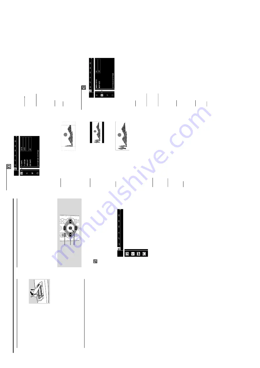
TV SHAPE
Select the aspect r
atio of the
TV to be connected.
If y
our
D
VD is not encoded to allo
w y
ou to change the aspect
ratio
, TV shape cannot be changed.
4:3 PS
(panscan)
Select this if y
ou ha
ve
a
con
ventional
TV set and y
our
D
VD is not f
o
rmatted fo
r
widescreen viewing, use this
setting.
A wide picture is
displa
yed on the whole
TV screen with a por
tion
automaticall
y cut off.
4:3 LB
(letterbo
x)
Select this if y
ou ha
ve
a
con
ventional
TV set and y
our D
V
D
is f
o
rmatted for widescreen
viewing,
use this setting.
Wide
bands is displa
yed on the upper
and lo
w
er por
tions of the
TV screen.
16:9
(widescreen)
Select this if y
ou ha
ve
a
widescreen
TV set,
use this
setting (y
ou m
u
st also set
your widescreen
TV to
“full
siz
e”).
TV SY
STEM
Allo
ws y
ou to select the colour system that cor
responds to
your TV
.
A
UT
O
Select this if the connected
TV is m
u
lti system,
select this
mode
.
The output for
mat will be in accordance with th
e
video signal of the disc
.
NTSC
Select this if the connected
TV is NTSC system,
select
this mode
. It will change the video signal of a P
AL disc
and output to NTSC
fo
rmat.
P
AL
Select this if the connected
TV is P
AL system,
select this
mode
. It will change the video signal of an NTSC disc
and output to P
AL for
mat.
VIDEO OUT
Set the
Video Output according to y
our video connection.
This setting is not required if y
ou are using the
VIDEO OUT
jack (y
ello
w) to connect the D
VD micro system to y
our TV
.
SCAR
T
Select this if y
ou ha
ve
connected the D
VD micro system
to y
our
TV using the Scar
t jack.
S-VIDEO
Select this if y
ou ha
ve
connected the D
VD micro system
to y
our
TV using S-Video jack
.
SCR SA
VER (Scr
een Sa
v
er)
OFF
Select this to disab
le the screen sa
ver function.
ON
Select this if y
ou wish to dim the
TV screen when th
e
disc pla
yback is stopped or paused for more than one
minute
.
This will prev
ent y
our displa
y device from
becoming damaged.
Sound Setup
DIGIT
AL OUTPUT
Allo
ws y
ou to specify the type of digital output suita
bl
e
fo
r
the optional audio equipment that connected through th
e
DIGIT
AL OUT at the rear of y
our D
VD micro system.
ALL
Select this if y
ou ha
ve
connected the digital output to
a
mu
ltichannel decoder receiv
er
.
PCM 96K
Select this if the optional audio equipment is capab
le of
processing digital signal input with sampling r
ates of 96 kHz.
PCM 48K
Select this if the optional audio equipment is incapable of
processing 96 kHz digital signal input
.
The signal will then
be con
ver
ted to a standard signal with sampling
ra
tes of
48 kHz.
OFF
Select this to deactivate the digital output
.
NIGHT MODE
Night function can also be accessed via the remote control.
OFF
Select this when y
ou want to enjo
y the sur
round sound
with its full dynamic r
ange
.
ON
Select this to level out the
vo
lume
. High v
o
lume outputs
will be softened and low volume outputs are brought
upward to an audible le
ve
l.
This f
eature is only a
vailabl
e
for mo
vies with Dolby Digital mode
.
Inser
ting batteries into the
r
emote contr
ol
1
Open the batter
y compar
tment.
2
Place the batter
ies in the
compar
tment with the cor
rect
polar
ity as indicated by
“
+
“ and
“
-
“
symbols.
3
Close the co
ve
r.
CA
UTION!
–
Remo
v
e
batteries if they ar
e e
xhausted or if th
e
remote is not to be used f
or a long time
.
–
Do not use old and ne
w or differ
ent types of
batteries in combination.
–
Batteries contain chemical substances,
so the
y
should be disposed off pr
operl
y.
Switching on the system
1
After completing all the connections
, connect the
A
C
po
w
er cord of the play
er to the po
w
er outlet.
2
Press
ST
ANDBY ON
to switch on the last selecte
d
source
.
3
Adjust the
SOURCE
button (or press
DISC
,
TUNER
or
A
UX/TV
on the remote) to select the input source
.
➜
The selected source will be displa
yed.
●
F
or vie
w
ing a D
VD or
VCD disc
,a
TV set needs to be
connected (refer to
“
Connections - Connecting a
TV
”).
Switch on the
TV and set to the co
rr
ect video in channel
(for exampl
e
, EXT1,
EXT2,
A
V1,
A
V2).
Ref
er to y
our
TV
instr
uction man
ual for details.
➜
The default screen appear
s on the
TV
.
System Setup (D
VD)
The system setup is ca
rri
ed out via the
TV
, enab
ling y
ou to
customise the D
VD micro system to suit y
our par
ticular
requirement.
If the pref
er
red options selected are not
availab
le on a disc
, then the disc’
s o
wn pref
erence will be
used.
IMPOR
T
ANT !
To
access the System Setup menu,
pla
yback m
ust
be stopped.
1,
5
2,
3
4
To
enter System Setup me
nu
1
In disc mode
, press
SY
STEM MENU
on the remote
.
➜
icon will be highlighted in the menu bar on the
TV
screen.
2
Press
4
to activate the System Setup menu.
3
Use
34
keys to select one of the setup menu options an
d
press
2
to enter the men
u.
4
Press
OK
to conf
ir
m y
our selection.
5
To
exit the System Setup menu,
press
SY
STEM MENU
or
OK
.
Pr
eparations
Pictur
e Setup
Sound Setup
Langua
g
e
Setup
F
eatur
e Setup
1-8
Summary of Contents for MC-D370/21M
Page 2: ...1 2 YUV AMPLIFIER MAIN 3 1CH AUDIO OUT PCB CONTROL LOCATION OF PCBS ...
Page 16: ...2 4 2 4 ...
Page 19: ...4 1 BLOCK DIAGRAM 4 1 ...
Page 20: ...4 2 WIRING DIAGRAM 4 2 ...
Page 22: ...5 2 5 2 VFD DRIVER PT6311 VFD DRIVER PT6311 ...
Page 23: ...5 3 5 3 AUDIO PROCESSOR NJW1136L INTERNAL BLOCK DIAGRAM AUDIO PROCESSOR NJW1136L ...
Page 26: ...PCB LAYOUT TOP VIEW 5 6 5 6 ...
Page 27: ...PCB LAYOUT BOTTOM VIEW 5 7 5 7 ...
Page 31: ...6 3 PCB LAYOUT TOP VIEW PCB LAYOUT BOTTOM VIEW ...
Page 41: ...6 CHANNEL ELECTRONIC VOLUME NJW1150M 8 3 8 3 6 CHANNEL ELECTRONIC VOLUME NJW1150M ...
Page 44: ...LAYOUT DIAGRAM AMPLIFIER BOARD COMPONENT SIDE 8 6 8 6 ...
Page 45: ...8 7 8 7 LAYOUT DIAGRAM AMPLIFIER BOARD SMD SIDE ...
Page 60: ...LAYOUT DIAGRAM MAIN BOARD COMPONENT SIDE 9 14 9 14 ...
Page 61: ...LAYOUT DIAGRAM MAIN BOARD SMD SIDE 9 15 9 15 ...
Page 65: ...10 3 10 3 POWER PCB LAYOUT ...
Page 69: ...11 3 PCB LAYOUT TOP VIEW PCB LAYOUT BOTTOM VIEW ...
Page 73: ...12 3 PCB LAYOUT COMPONENT SIDE PCB LAYOUT SMD SIDE ...


