background image

+12.5V (MC20)

(MC20)

+12.5V (MC20)

+12V_S (MC20)

-8V2
(MC20)

ETF (MC20)

+12V_S

MC20

-8V2

-8V2

Stabilizer
(MC20)

(MC20)

+12.5V

8 W (MC20)

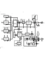
BLOCK DIAGRAM

5-1

5-1

PCS 104 564

MTF (MC10)

TAPE MODULE

SOURCE
SELECTOR

8 OHM

ECO6

TUNER MODULE

~

~

CD99

LCD

CD MODULE

POWER AMP

CONTROL

DIGITAL

DCC 

BUFFER

4 W (MC10)

+

-

R

R

+12V_S (MC10)

From 
Processor

From 
Processor

TAPE_REC

From 
Processor

From Tuner

A0/A1

From 
Processor

+5V6_S

+5V6_S

TAPE_REC

+5V6_S

PWM

+5V

+MOT (MC10)

+5V6S (MC10)

+MOT

+CD

AUX

+B

+MOT

+CD

ELECTRONIC

(Rock, Pop Jazz, I.S.)

MICRO
PROCESSER

To CD

To TAPE

To Tuner +5.6V

VOLUME

+5V6

Stabilizer

+12.5V

Stabilizer

RESET

+A

+12.5V

+5V6

+5V6

+5V6_S

+5V6_S

SHIFT 
REGISTER

RDS 
DECODER

ON / OFF

STAND_BY

CONTROL
LINES

ON / OFF

+B

D

D

FOR /22 ONLY

+12.5V

Backlight

D

M

ON / OFF

MC10

MPX

V

V

V

V

V

V

V

V

V

V

ON / OFF

V

V

V

V

V

V

+5V6_S

Summary of Contents for MC-20

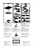
Page 1: ...NTS chapter Handling chip components and safety 1 1 MC 20 Technical Specification Service Tools 2 1 Service Measurement 2 2 Connections Controls 3 1 Disassembly Diagram 4 1 Instructions for use 3 2 to 3 6 CD Service Test Program 4 2 to 4 3 Block Diagram 5 1 Wiring Diagram 5 2 circuit diagram 6 1 FRONT BOARD layout diagram 6 2 circuit diagram 7 1 to 7 3 COMBI BOARD layout diagram 7 4 circuit diagra...

Page 2: ... essere collegato allo stesso potenziale che quello della massa delápparecchio tramite un braccialetto a resistenza Assicurarsi che i componenti e anche gli utensili con quali si lavora siano anche a questo potenziale Safety regulations require that the set be restored to its original condition and that parts which are identical with those specified be used Safety components are marked by the symb...

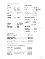
Page 3: ...CTION EQUIPMENT TECHNICAL SPECIFICATIONS GENERAL Mains voltage 21 21M 120 230 V 22 25 30 33 230 V Mains frequency 22 25 30 33 50 Hz 21 21M 50 60 Hz Battery remote 3 V R6 x 2 Power consumption normal 60 W Standby 3 W Dimension W x H x D 223 x 140 x 247 mm Weight 5 6 Kg AMPLIFIER Output power mains 2 x 8 W Speaker impedance 2 x 8 ohm Frequency response 100 Hz 10 kHz 4dB TUNER FM SECTION Tuning range...

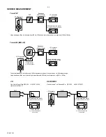
Page 4: ... 7122 707 89001 Tuner AM MW LW To avoid atmospheric interference all AM measurements have to be carried out in a Faraday s cage Use a bandpass filter or at least a high pass filter with 250kHz to eliminate hum 50Hz 100Hz RF Generator e g PM5326 Ri 50 L R LEVEL METER e g Sennheiser UPM550 with FF filter S N and distortion meter e g Sound Technology ST1700B DUT CD RECORDER Use Audio Signal Disc SBC4...

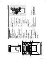
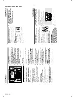
Page 5: ...B Dynamic Bass Boost enhances the bass DSC Digital Sound Control selects sound characteristics OPTIMAL ROCK JAZZ POP INCREDIBLE SURROUND creates a super enhanced stereo effect iR SENSOR infrared sensor for remote control Controls Notes for remote control First select the source you wish to control by pressing one of the source select keys on the remote control e g CD TUNER etc Then select the desi...

Page 6: ...ayback will continue without sound and the display shows MUTE To activate sound reproduction you can press MUTE again adjust the volume controls change source DS DBB MUTE SID Å VOLU RADIO RECEPTION Poor radio reception The signal is too weak adjust the antenna or connect an external antenna for better reception Increase the distance from TV or VCR TAPE DECK OPERATION Recording or playback cannot b...

Page 7: ...sc programme or if SHUFFLE REPEAT active searching is only possible within the same track Different play modes SHUFFLE and REPEAT You can select and change the various play modes before or during playback The play modes can also be combined with PROGRAMME SHUFFLE tracks of the entire disc programme are played in random order SHUFFLE and REPEAT ALL to repeat the entire disc programme continuously i...

Page 8: ...g through different RDS information Press RDS briefly and repeatedly to scroll through the following information if available Station name Programme type such as NEWS SPORT POP M Radio text messages Frequency Note If you press RDS and the RDS signal is not available NO RDS is displayed EON Enhanced Other Network allows you to search for an RDS station offering a certain programme type If EON is av...

Page 9: ...t of you and break out the left tab Recording on this side is no longer possible If however you wish to record over this side again cover the tabs with a piece of adhesive tape Synchro Start CD recording 1 Select CD source 2 Insert a disc and if desired programme track numbers 3 Press OPEN to open the tape door 4 Insert a suitable tape into the deck and close the tape door 5 Press RECORD to start ...

Page 10: ... The clock digits for the minutes flash 6 Turn VOLUME to set the minutes clockwise for minutes up anti clockwise for minutes down 7 Press TIMER ON OFF to confirm the time The timer is now set and activated Activating and deactivating TIMER In standby or during playback press TIMER ON OFF on the system once TIMER on the remote control Display shows TIMER if activated and disappears if deactivated A...

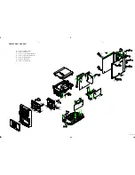
Page 11: ...LY DIAGRAM 4 1 4 1 PCS 104 191 A To remove Cabinet Rear B To remove CD Tray C To remove Tuner Board Bracket D To remove Combi Board Bracket E To remove Bottom Plate F To remove Tape Deck G To remove Front Board ...

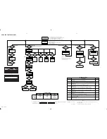
Page 12: ... 300ms have passed by innerswitch or sledgemotor problem E1002 Slide in error The sledge did not reach its inner position innerswitch is closed before approximately 6 seconds have pressed by innerswitch or sledgemotor problem W E1020 Focus search error The focus point has not been found within a certain time F W W E1001 Radial error Triggered when the radial servo is not on track for a certain tim...

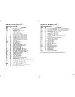
Page 13: ...utput programmable open drain VSSD1 33 1 digital ground 2 V2 V3 34 versatile I O input versatile pin 2 or output versatile pin 3 open drain WCLI 35 word clock iutput for data loopback to DAC SDI 36 serial data input for data loopback to DAC SCLI 37 serial bit clock input for data loopback to DAC RESET 38 power on reset input active LOW SDA 39 microcontroller interface data I O line open drain outp...

Page 14: ...12V_S MC10 From Processor From Processor TAPE_REC From Processor From Tuner A0 A1 From Processor 5V6_S 5V6_S TAPE_REC 5V6_S PWM 5V MOT MC10 5V6S MC10 MOT CD AUX B MOT CD ELECTRONIC Rock Pop Jazz I S MICRO PROCESSER To CD To TAPE To Tuner 5 6V VOLUME 5V6 Stabilizer 12 5V Stabilizer RESET A 12 5V 5V6 5V6 5V6_S 5V6_S SHIFT REGISTER RDS DECODER ON OFF STAND_BY CONTROL LINES ON OFF B D D FOR 22 ONLY 12...

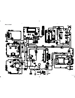
Page 15: ...WIRING DIAGRAM 5 2 5 2 PCS 104 193 ...

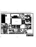
Page 16: ... 5g 6a 15 STEREO 8c 3487 2K2 3K9 3495 56K 3496 56K 150K 4 5V 4V 12 5V UNLESS OTHERWISE STATED 230V MAINS SUPPLY 6 4 2 T410 AM RESET TUNER COM1 7 8 9 3408 470K 1 10 11 12 13 14 15 16 2 3 4 5 6 FE ST VK N 1416 3412 10K 5402 470R 3481 2412 15p 10R 3400 2402 100u 2439 470p 2447 470p 470p 2435 1 2 T431 4400 EH B 1417 2426 220p 2442 T402 22p 3402 100R 3483 15K 2418 1n 3485 2K2 T451 T445 T425 T426 470R 3...

Page 17: ...GRAM 6 2 6 2 PCS 99 472 1 A B C D F G H I J E A B C D F G H I J E 2 3 4 5 6 7 8 9 10 11 12 13 1 2 3 4 5 6 7 8 9 10 11 12 13 A B C D F G H I J E A B C D F G H I J E 1 2 3 4 5 6 7 8 9 10 11 12 13 1 2 3 4 5 6 7 8 9 10 11 12 13 ...

Page 18: ... A 1 off ELECTRONIC VOLUME CONTROL from CD_L SERVO Logic Table to AUX Pop to 6500 1 2 3 4 5 6 7 8 9 10 11 12 13 14 15 1 2 3 4 5 CD 1 TUNER 0 uP Port Extension TAPE_R BKLT_ON TAPE_L AU_CLK from 1556 0 D_GND SOURCE SELECTOR Amplifier Part DBB B C D E F G H I 1550 A1 1551 B1 1552 B2 1553 C2 1554 D2 1555 E2 1556 G2 2500 A8 to A1 CD on Low 1 TU_EN MPX TAPE_L CD Board 0 3 0 56V 2 2 36V 0 2 9V 0 2 65V 0 ...

Page 19: ...DW93CFP 2345 D12 HEADPHONE SOCKET 3347 G8 T343 E4 T344 D4 3342 B11 3343 E9 6 2V 9330 B8 3346 D9 POWERSTAGE L 3349 G7 MUTE OFF ON Standby Mode Tuner Mode 1KHz df 22 5kHz DSC OPTIMAL DBB OFF INCR OFF VOLUME 20 LS BOX 3348 G7 1330 A13 to 3547 3548 E right 9 9V 11V 11V 0V 3 25V 0 2 2V V 2348 F10 2349 H10 2351 B6 4333 E5 0V G A forseen only 7333 H7 6332 G10 L 15 socket 12 B 7330 D6 3341 B11 F 2355 68 1...

Page 20: ... 7 8 9 16 17 18 19 20 10 11 12 13 14 A B C D E F 13V to 12 3V 0 14V 0 7V 12 9V Standby Mode PLATE G E F MC20 21 7V 19 8V 18 8V MC20 8 3V ac 8V ac 7 9V ac MC20 16 6V ac 16 1V ac 15 8V ac MC10 Recognition ETF_LOGIC MC20 MTF_MOTOR MC10 Mains Breakdown Low Power Standby L P S 10 11 12 13 14 15 forseen only 1250 16 17 2 3 4 5 MC20 10 6V 9 1V 8 5V MC20 0 4V 9 8V 9 2V MC20 8 4V 10 6V 9 8V 9 1V MC10 10 6V...

Page 21: ...COMBI BOARD LAYOUT DIAGRAM 7 4 7 4 PCS 99 476 1 2 3 4 5 6 7 8 1 2 3 4 5 6 7 8 1 2 3 4 5 6 7 8 1 2 3 4 5 6 7 8 A B C D E F G H A B C D E F G H A B C D E F G A B C D E F G ...

Page 22: ...F2 33 FM IF2 IN 5 FM OSC 8 I TUNE 17 TEA5762 7101 10 AF OUT 20 AFC 19 AFC 44 AGC 32 AM AFC 41 AM IF1 IN 36 AM IF2 2107 1u 56K 3141 BAS216 6106 22K 3134 7110 BC857B 6 7 8 2u2 2138 1120 FE BT VK N 1 2 3 4 5 1 2 3 4 6 7 8 5111 22K 3143 470R 3158 2143 220n T124 330R 3154 T123 T125 T111 3190 120R 120R 3191 BAS216 6120 1K 3144 100K 3156 2144 1u 47K 3171 3194 2K2 2132 470n 1132 C PAD 2118 2p2 220R 3105 2...

Page 23: ...inuous wave VRF 2mV D f 10kHz VRF 0 5mV as low as possible Use Service Testprogram By selecting the TUNER TEST test frequencies will be stored as preset frequencies automatically AM FRAME AERIAL FM 75Ω FM FRONTEND Birdy Filter ECO6 Sys Cenelec stage 2 270899 1101 B5 1102 B5 1103 C5 1110 B4 1120 A4 1130 A5 1131 C5 1132 A4 2106 B4 2107 B3 2128 B3 2129 B4 2133 C1 2138 B1 2144 B1 2162 A4 3142 C2 5102 ...

Page 24: ...a has to be used 2 RC network serves for damping the IF filter while adjusting the other one 4 MW has to be aligned before LW Waverange Input frequency Input Tuned to Adjust Output Scope Voltmeter FM 87 5 108MHz 65 81 74 87 5 108MHz FM MW version 9kHz grid 531 1602kHz as low as possible TUNER BOARD ECO6 Systems non Cenelec copperside view 2101 B5 2103 D4 2104 B4 2119 D3 2120 D3 2124 D3 2125 D3 212...

Page 25: ...C STABILIZER AFC VDD VSTABA AM IF MONO FM FRONTEND CONTROL XTAL AGC PRE CTRL AGC AM OSC AGC VCC2 FM OSC AM MIXER MIXER FM FM IF1 FRONTEND AM STEREO STEREO RDS only DISCRIMINATOR to from VERSION AM IF1 FM OSCILLATOR PROGR MPX Q multiplier MW OUTPUT PORTS to 1120 pin 5 ENABLE MPX BUFFER component mounted kHz VERSION DETECTION 00 02 FM MW LW VERSION PROGRAMMING COMPONETS VCO RIGHT 14 1 2 3 AM FRAME A...

Page 26: ...230V MC148 T2A MC118 T MC20 01 TO conn 1252 3 4 D E F 21 only C 3602 B4 3603 C4 1602 D3 1603 D3 F 2600 B3 DIPMATE 0014 MC10 only 1 2 3 4 7 10 12 16 2 3 4 5602 EI 57 35 1 3 5 6 220u 2600 DIPMATE 0015 1 5600 1 8 4 5 1N4148 6602 1N4148 6603 6600 1N4148 10M 3600 5604 EI 66 40 1 3 5 6 8 12 13 17 6601 1N4148 6 5603 EI 28 12 3 1 3 4 3 15A 1601 4K7 3601 EI 57 30 1 3 5 6 7 9 10 12 13 16 5601 MC20 only 1 2 ...

Page 27: ...902 C2 3903 C3 3904 C3 6901 A1 6902 B1 To Front Board 6903 B1 6904 A2 6905 B2 6906 B2 6907 A2 6908 B2 6909 B2 6910 A3 6911 B3 3903 120R 120R 3904 6910 LTL 16KGE 8901A 6909 LTL 16KGE 120R 3902 6908 LTL 16KGE 3901 120R 6906 LTL 16KGE 6907 LTL 16KGE 6905 LTL 16KGE 6903 LTL 16KGE 6904 8901B LTL 16KGE 6901 1 A B C D E F G A B C D E F G 2 1 2 LED BOARD LAYOUT DIAGRAM ...

Page 28: ...84 2K2 5 MOTOR 3622 4K7 27K 3613 100K 3685 100K M M 3612 56K 3686 100K 47K 27K 3602 M 470R 3630 3674 1706 1 2 3 4 5 6 7 M M 3678 3676 47K M HS Vcc DECK AB L 5 3618 10K 2 3 4 5 6 7 8 2621 1n 2 3 4 5 6 7 8 9 1760 1 27K 3608 P 3620 4K7 3605 2K2 100R 3687 4785 P 2K2 3609 Os 10 Os 1 STR 16 VDD VSS 8 100n 2625 HEF4094BT 7610 3 CP 2 D 15 E0 O0 4 O1 5 6 O2 O3 7 O4 14 O5 13 O6 12 O7 11 9 MOTOR P 4K7 3625 1...

Page 29: ...EFT RIGHT Inject 1kHz 8 85mV 3 4 or via 3 4 or via 1 2 or LEFT RIGHT RECORD B RECORD B PLAY B PLAY B mV meter THD meter check check limits see fig 2 3 RECORDED CASSETTE RECORDED CASSETTE 995mV 750mV 1 5dB 3773 check figure 1 f Hz level dB 8dB 6dB 12 5k 4k 250 80 8dB f Hz level dB 8dB 10dB HSD 6dB 10k 4k 250 100 8dB 10dB HSD figure 2 check SBC419A 4822 397 30069 SBC420 4822 397 30071 SBC420 3150Hz ...

Page 30: ... For Provision Only See Variant Table for details L Not For Single Deck Variant A2 1 NS Chrome 1 S4 0 Pb Ferro Dubbing 12K 3769 L L 12 3776 6K8 REC_R A REC A 220R 3706 A REC_L P A 150K BC557B 7782 2782 4n7 A B4 330p 2709 REC_L 3775 4R7 B4 A 10n 2717 P 1n 2727 150K 3711 6R8 15n 2784 3710 3709 6R8 A 7792 BC847B P P A 100n 2744 BC847B 7791 33n 2719 3754 1M 2725 4n7 6770 1N4148 A 2708 470p 7785 J111 R...

Page 31: ...3 4 2 1 6 5 3 4 2 1 6 5 RECORDER BOARD ETF6 LAYOUT DIAGRAM 11 4 11 4 PCS 104 199 ...

Page 32: ...C5 3889 D5 3890 D2 3891 E2 3892 D2 3893 D2 3894 E3 3895 E2 3896 E2 3897 D2 3898 D2 3899 D2 3900 D4 4801 E5 4802 F2 4804 D4 4805 E4 4806 D5 4807 E2 4808 D5 4809 D5 4810 B2 4812 B4 4813 B3 4814 B3 4815 A4 4823 C2 4824 B2 4828 B2 4831 B3 4832 B3 4838 C5 4845 D2 4847 E1 4848 B4 4850 G5 4853 F2 4856 F5 4857 B4 4859 B5 4863 C5 4865 A4 4866 B4 4872 F2 4877 H5 4881 G5 4884 E2 4885 G5 4886 G1 4888 F2 4889 ...

Page 33: ...03 82p 470R 15K 3843 1K 100K 3892 3816 47K 3859 3893 100K 2818 47n 2822 1n5 2826 47n 7802 A A 1 Y 2 82p 2805 33R 3827 3745 10R 2831 1u 3829 100R 3 3V 10K 3896 470R 22K 3831 3839 4K7 3841 3803 27K 47K 3861 3 3V 2819 33p LDON 2806 82p drive_recognition 3K9 3858 180p 2865 47u 2840 22K 3834 5V 180p 3807 1K5 2864 3890 100K 3815 4K7 3856 68K 3860 1K 100K 3891 3862 1K 3728 47R 3servo 3801 150K 7807 BC847...

Page 34: ... 404 406 407 408 409 418 417 419 423 421 422 424 426 428 429 431 432 433 434 436 437 438 439 441 442 443 444 446 SCREW LIST 1 T2 x 10 2 T2 5 x 10 3 T3 x 6 4 T3 x 8 5 T3 x10 6 T3 x12 7 P W C2 5 x 10 8 P W T3 x 6 9 P W T3 x 10 6 412 414 413 411 427 CD TAPE TUNER TIMER AUX SLEEP DBB DSC INC SU RR MUTE REPEA T PROGR AM SHUFF LE SIDE NEWS T A VOLUM E 501 502 503 504 506 416 ...

Page 35: ... 60010 Front Cab RDS Assy For 22 446 4822 466 93148 Spacer 409 4822 492 11344 Spring Compression 4822 303 50063 FM Antenna Wire 411 4822 529 10322 Damper Assy 3140 115 27770 Instructions Manual For 21 21M 30 412 4822 492 11345 Spring Tension 3140 115 27780 Instructions Manual For 22 413 4822 402 11246 Bracket Cassette 414 4822 402 10621 Push Catch 416 3140 114 36200 Front Knobs Source 417 3140 114...

Page 36: ...L 44 482227711749 Mode Switch 20 482228111069 Solenoid 71 482249211542 Spring 24 482252811304 Flywheel Assy L 72 482249211546 Spring 33 482252811305 Flywheel Assy R 101 482253212931 Washer 34 482235810271 Belt 102 482253212934 Washer 36 482236110808 Motor Assy 103 482253212932 Washer 40 482226511535 Connector Socket 8P 104 482253212933 Washer 41 482227613704 Leaf Switch 105 482253212935 Washer Not...

Page 37: ...212614076 220nF 80 20 25V 2513 482212613692 47F 1 NP0 63V 2514 482212613692 47F 1 NP0 63V 2515 482212233177 10nF 20 X7R 50V ELECTRICAL PARTSLIST COMBI BOARD RESISTORS RESISTORS 3250 482205120471 470R 5 0 1W 3348 482205120223 22K 5 0 1W 3251 482211711449 2K2 1 0 1W 3349 482211710834 47K 1 0 1W 3252 482205120472 4K7 5 0 1W 3350 482211710834 47K 1 0 1W 3253 482205120472 4K7 5 0 1W 3351 482205110102 1...

Page 38: ...N4003G 3587 482205120392 3K9 5 0 1W 6263 482213031878 Diode 1N4003G 3588 482205120392 3K9 5 0 1W 6264 482213031878 Diode 1N4003G 3589 482211683872 220R 5 0 5W 6265 482213031878 Diode 1N4003G 4260 482205120008 Jumper 6266 482213030621 Diode 1N4148 4261 482205120008 Jumper 6267 482213030621 Diode 1N4148 4262 482205120008 Jumper 6268 319801058280 Diode BZX79 B8V2 4263 482205120008 Jumper 6269 4822130...

Page 39: ...532212234099 470pF 10 X7R 63V 3443 482205023303 33K 5 0 1W 2449 532212234099 470pF 10 X7R 63V 3444 482211652175 100R 5 0 5W ELECTRICAL PARTSLIST FRONT BOARD RESISTORS RESISTORS 3445 482211711449 2K2 1 0 1W 3496 482205120154 150K 5 0 1W 3446 482211713579 220K 1 0 1W 3497 482211710833 10K 1 0 1W 3447 482211710833 10K 1 0 1W 3498 482211710833 10K 1 0 1W 3448 482211652243 1K5 5 0 5W 3499 482205120223 ...

Page 40: ...3R 5 0 1W 3884 482205110102 1K 2 0 25W 3828 482205120479 47R 5 0 1W 3886 482211710833 10K 1 0 1W 3829 482205120101 100R 5 0 1W 3887 482211710833 10K 1 0 1W 3830 482205120472 4K7 5 0 1W 3888 482205120472 4K7 5 0 1W 3835 482205120223 22K 5 0 1W 3889 482205110102 1K 2 0 25W 3836 482211710833 10K 1 0 1W 3890 482211710837 100K 1 0 1W 3837 482205120471 470R 5 0 1W 3891 482211710837 100K 1 0 1W 3838 4822...

Page 41: ...3575 220pF 5 NP0 63V 3180 482211710833 10K 1 0 1W 2147 482212233575 220pF 5 NP0 63V 3190 482205120121 120R 5 0 1W 2148 482212233127 2 2nF 10 X7R 63V 3191 482205120121 120R 5 0 1W 2149 532212232659 33pF 5 50V 3192 482211713577 330R 1 1 25W 2150 482212613838 100nF Y5V 50V P80M20 3193 482211713577 330R 1 1 25W 2159 532212232659 33pF 5 50V 3194 482211711449 2K2 1 0 1W 2162 482212481151 22µF 50V 3195 4...

Page 42: ...212613695 82pF 1 NP0 63V 4106 482205120008 Jumper 2141 482212613838 100nF Y5V 50V P80M20 4107 482205120008 Jumper 2143 482212614076 220nF 25V P8020 4108 482205120008 Jumper 2144 482212421913 1µF 20 63V COILS FILTERS 2145 482212233575 220pF 5 NP0 63V 2146 482212233575 220pF 5 NP0 63V 5102 482215771634 MW Aerial 2147 482212233575 220pF 5 NP0 63V 5109 482224270665 Filter SFE10 7MS3 A 2148 48221223312...

Page 43: ... 10R 5 0 1W 2765 482212440433 47µF 20 25V 3714 482205120109 10R 5 0 1W 2769 532212234099 470pF 10 X7R 63V 3715 482205120182 1K8 5 0 1W 2770 532212234099 470pF 10 X7R 63V 3716 482205120182 1K8 5 0 1W 2780 482212481151 22µF 50V 3717 482211711449 2K2 1 0 1W ELECTRICAL PARTSLIST RECORDER BOARD ETF6 RESISTORS RESISTORS 3718 482211711449 2K2 1 0 1W 3774 482211710833 10K 1 0 1W 3719 482205120472 4K7 5 0 ...

Page 44: ...13042804 Trans BC817 25 7782 482213044568 Trans BC557B 7783 482213060511 Trans BC847B 7784 482213060373 Trans BC856B 7786 482213063494 Trans J111 7787 482213060511 Trans BC847B 7791 482213060511 Trans BC847B ELECTRICAL PARTSLIST LED BOARD RESISTORS 3901 482205120121 120R 5 0 1W 3902 482205120121 120R 5 0 1W 3903 482205120121 120R 5 0 1W 3904 482205120121 120R 5 0 1W DIODES 6901 932203320682 LED TL...

Reviews: