26
75
Ω
L
AUDIO
R
MONITOR
OUT
AV1
AV2
VIDEO
S-VIDEO
POWER
SLEEP
A/CH
STATUS/EXIT
CC
CLOCK
RECORD
TV
VCR
ACC
SMART
SMART
SMART
SOUND
PICTURE
MENU
SURF
VOL
CH
MUTE
1
2
3
4
5
6
7
8
9
0
TV/VCR
SWAP
SOURCE POSITION
FREEZE
PIP ON/OFF
SAP
ON
AVL
ON
INPUT
©
SLEEPTIMER
OFF
SmartLock
©
ANTENNA
EXT 1
EXT 2
4
5
6
3
2
AUDIO OUT
R L
S-VIDEO
OUT
ANT/CABLE
OUT
75
Ω
L
AUDIO
R
out
in-2
in-1
VIDEO
S-VIDEO
1
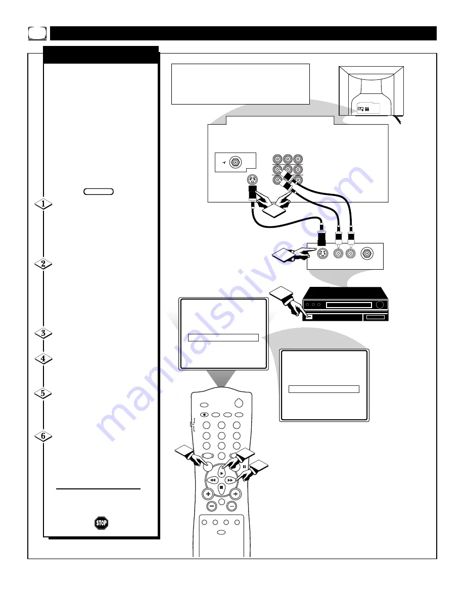
The S(uper)-Video connection on
the rear of the television can give
you better picture detail and clar-
ity, for the playback of S-VHS
VCR tapes, or Digital Video Discs
than the normal antenna picture
connections.
Note: The accessory device being
used must have a S-Video Output
to complete this connection. The
following steps show the connec-
tions to the S-VIDEO and
AUDIO IN 2 input jacks.
Connect the S-VIDEO
CABLE to the S-VIDEO input
jack on the rear of the television,
then the AUDIO (red and white)
to the AUDIO AV2 (left and right)
jacks on the rear of the TV.
Connect the S-VIDEO
CABLE to the S-VIDEO output
jack on the accessory device.
Then connect the red and white
AUDIO CABLES to the AUDIO
(left and right) output jacks on the
rear of the accessory device.
Turn the VCR (or Digital
Video Disc Player) ON.
Press the MENU button on
the remote to display the onscreen
menu.
Press the CURSOR UP
▲
or
CURSOR DOWN
■
buttons
until the word INPUT is highlight-
ed.
Press the CURSOR RIGHT
©©
or CURSOR LEFT
§§
button to display the INPUT menu
(ANTENNA, EXT 1, EXT 2). Use
the CURSOR UP
▲
or DOWN
■
buttons to select EXT 2.
Now your ready to use the accesso-
ry device with the S-Video outputs.
AUDIO IN
(RED/WHITE)
H
OW TO
U
SE THE
A
UDIO
/V
IDEO
I
NPUT
J
ACKS
BEGIN
S-VIDEO CABLE
(NOT SUPPLIED)
DBS, DVD, Video Game, etc.
(EQUIPPED WITH S-VIDEO AND
AUDIO OUTPUT JACKS)
BACK OF ACCESSORY
S-V
IDEO
I
NPUT
BACK OF TV
NOTE: If there is an accessory device plugged into
the S-VIDEO jack and one plugged into the VIDEO
IN 2 jack, the video signal coming from the S-VIDEO
plug will be dominate when tuned to EXT 2 within
the INPUT control.


