© Koninklijke Philips Electronics N.V. 2006. All rights reserved.
User manual
Rev. 01 — 12 January 2006
120
Philips Semiconductors
UM10161
Volume 1
Chapter 11: I
2
C interfaces
can be a useful capability but intrinsically limits alternate uses for the same pins if the I
2
C
interface is not used. Seldom is this capability needed on multiple I
2
C interfaces within the
same microcontroller.
11.4 Pin description
11.5 I
2
C operating modes
In a given application, the I
2
C block may operate as a master, a slave, or both. In the slave
mode, the I
2
C hardware looks for its own slave address and the general call address. If
one of these addresses is detected, an interrupt is requested. If the processor wishes to
become the bus master, the hardware waits until the bus is free before the master mode is
entered so that a possible slave operation is not interrupted. If bus arbitration is lost in the
master mode, the I
2
C block switches to the slave mode immediately and can detect its
own slave address in the same serial transfer.
11.5.1 Master Transmitter mode
In this mode data is transmitted from master to slave. Before the master transmitter mode
can be entered, the I2CONSET register must be initialized as shown in
. I2EN
must be set to 1 to enable the I
2
C function. If the AA bit is 0, the I
2
C interface will not
acknowledge any address when another device is master of the bus, so it can not enter
slave mode. The STA, STO and SI bits must be 0. The SI Bit is cleared by writing 1 to the
SIC bit in the I2CONCLR register.
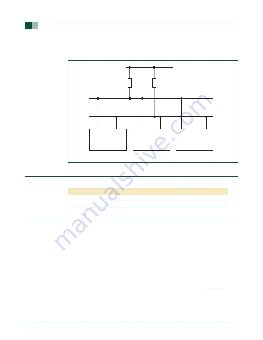
Fig 23. I
2
C-bus configuration
OTHER DEVICE WITH
I
2
C INTERFACE
pull-up
resistor
OTHER DEVICE WITH
I
2
C INTERFACE
LPC2101/02/03
SDA
SCL
I
2
C bus
SCL
SDA
pull-up
resistor
Table 117: I
2
C Pin Description
Pin
Type
Description
SDA0,1
Input/Output
I
2
C Serial Data.
SCL0,1
Input/Output
I
2
C Serial Clock.


