- 9 -
1. Application Object
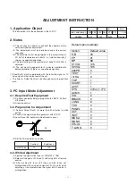
This instruction is for the application to the LCD TV.
2. Notes
(1) This set uses an adapter, so connect the adapter and the
set correctly before adjustment.
(2) The adjustment must be performed under the correct
sequence.
(3) The adjustment must be performed in the circumstance of
25! 5cC of temperature and 65±10% of relative humidity if
there is no specific designation.
(4) The input voltage of the receiver must keep 220V, 60Hz in
adjusting.
(5) The set must be operated for 30 minutes preliminarily
before adjustment if there is no specific designation.
[ Ô Heat RunÕ must be performed with the full white signal or TV
noise signal in the internal part of the set.
[ The time for Ô Heat RunÕ can be changed owing to production
plan.
3. PC Input Mode Adjustment
3-1. Required Test Equipment
(1) A pattern generator being in proportion to VG819 ; Pattern
of 64 tones
(2) A remote control
3-2. Preparation for Adjustment
(1) Perform Ô Heat RunÕ for more than 30 minutes in white
pattern.
(2) Connect the signal of pattern generator with LCD TV.
(3) Lean the set 45¡ backward. (Adjustment is easy.)
(4) Set the PC mode menu as below.
3-3. White Adjustment
(1) Approve the signal of 64 tones of XGA(1024 * 768).
(2) Select all the gain of R, B and G with using ADJ of remote
control.
(3) After making 62 tones, 63 tones and 64 tones not
distinguished with using each signal of R, G and B, finish
adjusting at the moment when the signal 62, 63 and 64 is
distinguished.
ADJUSTMENT INSTRUCTION
45¡
Initial Value
Contrast
70
Brightness
100
R
0.63 0.34
0x02
G
0.30 0.60
0x03
B
0.14 0.10
0x04
Error
! 0.03
Register
Color Coordinates(x,y)
AD9884
45¡
Initial Value
Contrast
70
Brightness
100
R
0.63 0.34
0x02
G
0.30 0.60
0x03
B
0.14 0.10
0x04
Error
! 0.03
Register
Color Coordinates(x,y)
AD9884
45¡
Initial Value
Contrast
70
Brightness
100
R
0.63 0.34
0x02
G
0.30 0.60
0x03
B
0.14 0.10
0x04
Error
! 0.03
Register
Color Coordinates(x,y)
AD9884
45¡
Initial Value
Contrast
70
Brightness
100
R
0.63 0.34
0x02
G
0.30 0.60
0x03
B
0.14 0.10
0x04
Error
! 0.03
Register
Color Coordinates(x,y)
AD9884
Default option settings
Option
Default value
S-B
23
FP
21
NP
89
S1VOL
105
S2VOL
105
200PR
0
TEXT
1
I II SA
0
TOP
1
SCART
1
A2 ST
1
SYS
0 (Eu), 1 (Fr)
ACMS
1
VOL
0
BBACK
0
LANG
6
TSS
0
PANEL
0
IICT
0
INVT
0
MD SA
0
MONO
0
CH+AL
0
T-LANG
0
Summary of Contents for LC1.15E
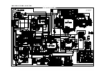
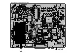
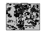
Page 12: ...Main Board for LC151X01 A3 LCD Panel Top Side ...
Page 13: ...Main Board for LC151X01 A3 LCD Panel Bottom Side ...
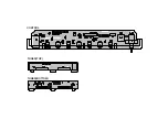
Page 14: ...CONTROL TUNER TOP TUNER BOTTOM ...
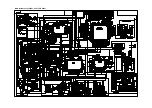
Page 15: ...Main Board for LC151X01 C3P1 LCD Panel ...
Page 16: ...Main Board for LC151X01 C3P1 LCD Panel Top Side ...
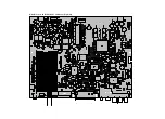
Page 17: ...Main Board for LC151X01 C3P1 LCD Panel Bottom Side ...
Page 18: ...CONTROL TUNER TOP TUNER BOTTOM ...
Page 21: ...EXPLODED VIEW 112 540 500 550 521 541 120 530 310 400 401 410 ...

