Directions for Use
EN 8
L04L AA
3.
S
IDE
AV C
ONNECTIONS
5
A
udio and V
ideo Side Inputs ar
e
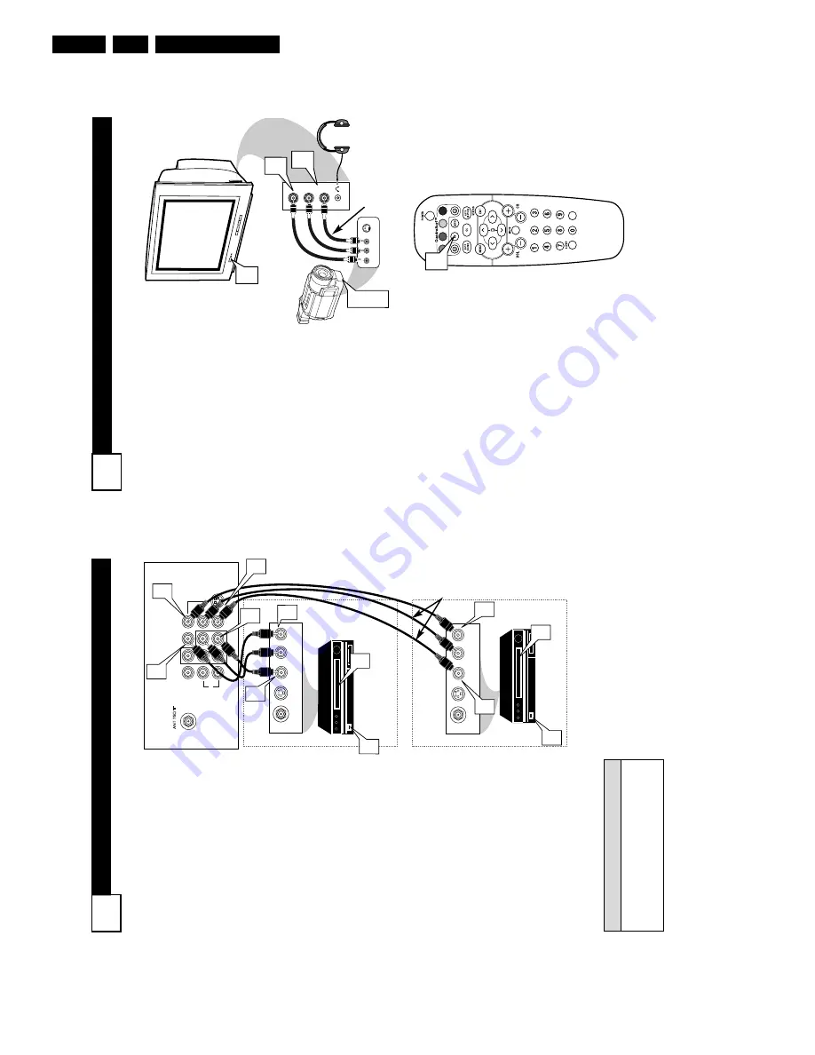
available for a quick connec-
tion of a VCR, to playback video
fr
om a camera, or attach a gam-
ing device. Use the
A
V
button on
the r
emote contr
ol to tune these
inputs.
1
Connect the video (yellow)
cable
from the
V
ideo output
on the Camera (or accessory
device) to the
V
ideo (yellow)
Input located on the SIDE of
the TV
.
2
For
Ster
eo Devices:
Connect
the audio cable (red and
white) from the
Audio Left
and Right Outputs on the
Camera to the
Audio In
(white) jack on the SIDE of
the television.
For
Mono Devices:
Connect
one end of the audio cable
from the
Audio Out jack on
the device to the
Audio In
(white) jack on the SIDE of
the television.
3
T
urn the
TV
and the accesso-
ry device ON.
4
Pr
ess the
A
V
button
on the
remote control to tune the
TV
to the side input jacks.
“Front” will appear on the
TV
screen.
5
Pr
ess the PLA
Y
䊳
button
on the accessory device to
view playback, or to access
the accessory device (camera,
gaming unit, etc.).
VIDEO
AUDIO
L
R
Front
S-VIDEO
VIDEO
AUDIO
LEFT RIGHT
3
1
2
3
5
VOL
4
Side Jack panel
of TV
Audio
Cables
V
ideo
Cable
Jack Panel of
Accessory Device
Optional
Headphones
AV (A
UDIO
/V
IDEO
) I
NPUT
C
ONNECTION
4
L/Mono
Monitor out
VIDEO
S-VIDEO
A
V
1 in
Y
Pb
Pr
A
V
2 in
AUDIO
R
COMPONENT
VIDEO INPUT
AUDIO OUT
R L
S-VIDEO
OUT
ANT/CABLE
OUT
VIDEO
OUT
3
AUDIO OUT
R L
S-VIDEO
OUT
ANT/CABLE
OUT
VIDEO
OUT
3
4
5
7
1
2
4
2
1
5
7
Audio and video cables are not sup-
plied with the
TV
, but are available
from Philips or electronics retailers.
H
ELPFUL
H
INT
Audio In
(Red and
White)
VCR
T
wo (or accessory
device) (Equipped with
V
ideo and
Audio Output Jacks)
V
ideo In
(Y
ellow)
Back of
VCR
Back of
TV
AV
1
Connection
A
V2 Connection
VCR One (or
accessory device) (Equipped
with Audio
and
V
ideo
Output
Jacks)
T
he TV’
s audio/video input jacks
ar
e for dir
ect pictur
e and sound
connections between the TV
and a
VCR (or similar device) that has
audio/video output jacks.
Both the
AV
1
and
A
V2 Input Jack connections
ar
e shown on this page, but either
one can be connected alone. Follow
the easy steps below to connect your
accessory device to the
A
V
1
and A
V
2
IN Jacks located on the back of the
TV
.
1
Connect the
VIDEO (yellow)
cable
to the
VIDEO
AV
1
IN
(or
A
V2 IN) jack on the back of the
TV
.
2
Connect the
AUDIO (r
ed and
white) cables
to the
AUDIO (left
and right)
AV
1
IN
(or A
V2
in)
jacks on the rear of the
TV
.
3
Connect the
VIDEO (yellow)
cable
to the
VIDEO
OUT
jack on
the back of the
VCR (either one
or two) or accessory device being
used.
4
Connect the
AUDIO (r
ed and
white) cables
to the
AUDIO (left
and right) OUT
jacks on the rear
of the
VCR (either one or two) or
accessory device being used.
5
T
urn the
VCR (either
one or
two) or
accessory device and
the TV
ON.
6
Pr
ess the
A
V
button to set the
TV to its
A
V1or
A
V2 channel.
7
W
ith either of the
VCRs (or
accessory devices) ON and a pre-
recorded tape (CD, DVD, etc.)
inserted,
pr
ess the PLA
Y
button
to view the tape on the television.
Summary of Contents for L04L
Page 36: ...Service Modes Error Codes and Fault Finding EN 36 L04L AA 5 E_06532_012 eps 130204 ...
Page 58: ...58 L04L AA 7 Circuit Diagrams and PWB Layouts Layout Mono Carrier Part 1 Bottom Side Part 1 ...
Page 93: ...Spare Parts List EN 93 L04L AA 10 10 Spare Parts List Not applicable ...
Page 94: ...Revision List EN 94 L04L AA 11 11 Revision List First release ...


