


3 - 3
3 - 3
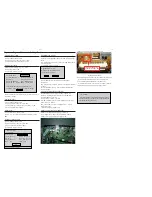
SERVICE POSITIONS
Note:In some service positions the components or copper patterns of one board may risk touching its neighbouring pc boards or
metallic parts. To prevent such short-circuit use a piece of hard paper or other insulating material between them.
Dismantling of the DVD Module
1) Loosen 3 screws “L” at the power PCB bracket bottom to remove DVD module as shown in fi gure 13.
L
Figure 13
Dismantling of the VFD+LED+DVD LED PCB
1) Loosen 3 screws “M” on the VFD PCB to remove it as shown in fi gure 14.
2) Loosen 2 screws “N” on the LED PCB to remove it as shown in fi gure 15.
3) Loosen 2 screws “O” on the door LED PCB to remove it as shown in fi gure 16.
4) Loosen 2 screws “P” at the DVD door lens ass’y to remove it as shown in fi gure 17.
5) Loosen 4 screws “Q” at the touch PCB bracket as shown in fi gure 18
M
Figure 14
N
O
P
Figure 15
Figure 16
Figure 17
Q
Figure 18
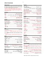
Summary of Contents for HTS5200
Page 9: ...2 2 2 2 REPAIR INSTRUCTIONS One ...
Page 10: ...2 3 2 3 REPAIR INSTRUCTIONS Two ...
Page 11: ...2 4 2 4 REPAIR INSTRUCTIONS Three ...
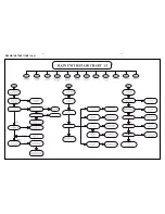
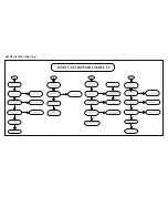
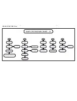
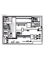
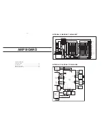
Page 15: ...4 1 4 1 BLOCK DIAGRAM ...
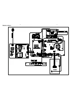
Page 16: ...4 2 4 2 WIRING DIAGRAM V3 V4 V1 V2 ...
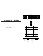
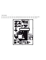
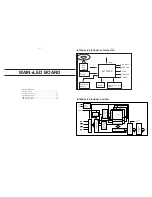
Page 33: ...9 1 9 1 TOUCH BOARD TABLE OF CONTENTS Circuit Diagram 9 2 PCB Layout Top View Bottom View 9 3 ...
Page 37: ...11 1 REVISION LIST Version 1 0 Initial release Version 1 1 Update chapter 1 2 ...