2 - 3
2 - 3
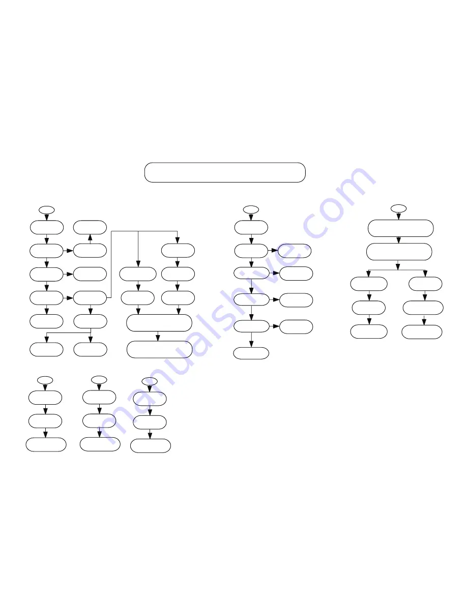
REPAIR INSTRUCTION (Part Three)
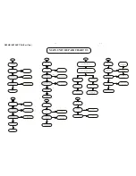
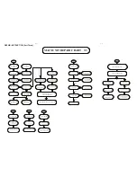
MAIN UNIT REPAIR CHART 3/3
L
Tuner No Sound
Output
Check CN301 Pin9= +9V
Check CN301Q901 ZD904
No
And Its Conjoint Parts
Check SW Power
See B
Yes
Check CN1 to CN301
Cable Loose or INT
Check CN1 Pin2/Clock
Pin3/Data,Pin4/CE
Affirm Correct
Yes
No
Check IC102 IC108
And Its Conjoint Parts
No
Check IC1 And
No
Its Conjoint Parts
Check VT Valtage
No
Low Freq=0.8--1.8V
Hi Freq=8.0--9.0V
Check IC1 OSC Input
Pin5---AM OSC
VT No Change
Pin3---FM OSC
Repair FM osc Section
And Its Conjoint Parts
No AM
No FM
L6 or DT4
Repair AM osc Section
And Its Conjoint Parts
L12 or DT5
Check Repair CN302 IC301
And Its Conjoint Parts
Check CN1 L12 CF3
And Its Conjoint Parts
OK
Check CN302 IC301
And Its Conjoint Parts
Check CF2 And
Its Conjoint Parts
L6 DT4
And Its Conjoint Parts
AM
Fu
n
ct
io
n
No
So
u
n
d
FM Function No Sound
OK
OK
OK
OK
Check IC1 X1 C39
And Its Conjount Parts
OK
Check Main Pcb Of Tuner Input Circuit
O
HDMI No Output
Yes
Insert And Pull out HDMI
cable
See C
OK
CheckQ610 Q611 Q609
And Conjoint Parts
No
Check IC602 3.3V And 1.8V
Check Q203 Q204
And Conjoint Parts
No
OK
Check C300
CheckC300
And Conjoint Parts
No
OK
Check IC602 PIN72:ASPDIF
CheckIC602 IC208
And Conjoint Parts
No
PIN77:ALCK
M
No Svideo output
Check JK701 Pin1 Pin3
Video signal
Yes
Check IC208 PIN133 PIN140
To JK701 Conjoint Parts
p
No CVBS output
Check JK701 Pin5
Video signal
Yes
Check IC208 PIN134
To JK701 Conjoint Parts
Q
No Y Pr Pb output
Check JK702 Pin12 Pin4
Pin5 Video signal
Yes
Check IC208 PIN137 PIN138
pin139 To JK702 Conjoint Parts
Check IC403 PIN8 +12V
And Its Conjoint Parts
Check IC505 PIN29--32
And Its Conjoint Parts
OK
Check IC701
Its Conjoint Parts
OK
OK
OK
NO SCART OUTPUT
OK
S
AUDIO
VIDEO
Repair IC505
And Its Conjoint Parts
Check IC208 PIN137 PIN138
pin139 Its Conjoint Parts
Check IC208 PIN134
Its Conjoint Parts
Check SCART OUTPUT


