3 - 1
3 - 1
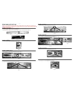
DISASSEMBLY INSTRUCTIONS
Dismantling of the IR Board
gure 9.
Figure 3
Dismantling of the Rear Cabinet
1) Loosen
Figure 2
Figure 4
Figure 8
Dismantling of the Main Board
1) Loosen
Figure 9
Figure 6
Figure 7
Figure 1-1
Dismantling of the Power Board
gure 8.
Dismantling of the MP3 Board
1) Loosen
B
Dismantling of the Main Board Bracket
1) Loosen
C
D
E
Dismantling of the Led Board
1) Loosen
Figure 5
F
H
I
Dismantling of the Key Board
gure 5.
G
A
15
Figure 1-2
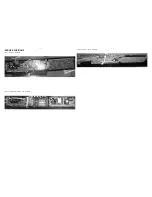
2) Lifting the front cabinet upwards and pull it right until the MP3 Links Jack out the cabinet as shown in figure 1-2.
on the rear cabinet as shown in figure 1-1.
Note:In some service positions the components or copper patterns of one board may risk touching its
neighbouring pc boards or metallic parts. To prevent such short-circuit use a piece of hard paper or other
insulating material between them.
Summary of Contents for HTS3111/12/05
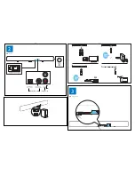
Page 13: ...4 3 4 3 4 EN Switch on 5 EN Select your audio source 1 3 2 AUX OPTICAL ...
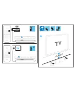
Page 14: ...4 4 4 4 1 14cm 5 5 2x 2 5cm 2x EN Wall mount the soundbar MP3 LINK COAXIAL ...
Page 23: ...7 1 7 1 KEY BOARD TABLE OF CONTENTS Circuit Diagram 7 2 PCB Layout Top Bottom View 7 3 ...
Page 30: ...9 1 9 1 LED BOARD TABLE OF CONTENTS Circuit Diagram 9 2 PCB Layout Top Bottom View 9 3 ...
Page 33: ...10 1 10 1 Mechanical Exploded View Audio Stero RC Note A1 1 2 3 B1 14 15 C1 16 17 D1 19 20 21 ...
Page 34: ...11 1 REVISION LIST Version 1 0 Initial release ...


