background image

GC9241

10-12

REPAIR INSTRUCTIONS

-  Due to the high wattage of the iron, only the specified cord set must be used.
-  Should damage be observed on the 

HOSE CORD MOUNTED ASSY 15

 or 

CORD SET 44

, they must be replaced. 

Continued usage is not allowed.

-  When replacing the 

MICROSWITCH ASSY 12

, please dress the 2 attached wires such that they are free of tension. Pulling force 

on the wires may affect the steam triggering.

-  To avoid damage to the sealing & components of the 

BOILER ASSY 36

NEVER

 clean the boiler assy with vinegar, descaling 

agent or other corrosive chemicals.

- When replacing 

ELECTROVALVE 37

 or 

PUMP ASSY 31

, please be reminded to apply loctite at the joints for good sealing.

-  After the product has been repaired, it should function properly and has to meet the safety requirements & legal regulations as 

laid down & officially established at this moment.

-  The following tests are common checks that are conducted on a repaired product before it is returned to the consumer.

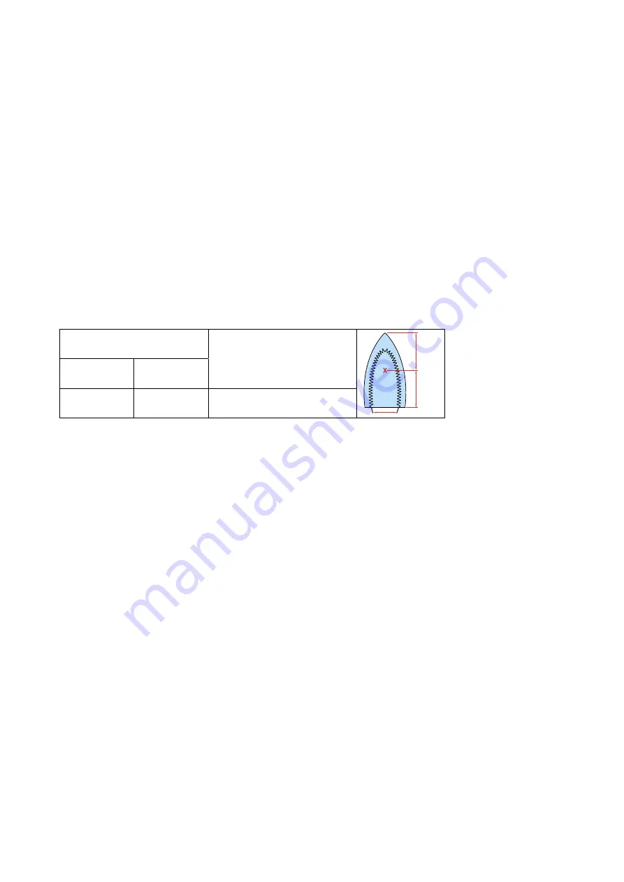
1. Soleplate temperature

Check that soleplate temperature is within below requirement.

Measure the temperature of the soleplate after the iron has reached steady state i.e connected to the mains for at least 15 minutes. 
The table below shows the temperature requirement.

Soleplate temperature (Deg C)

Materials, for example

Test-

point

==

Minimum

Maximum

120

143

All fabric types

2. Leakage current

Check that leakage current is within IEC requirement.

Measure leakage current between LIVE/NEUTRAL & EARTH.
IEC requirement is that at 230 V supply, the EARTH leakage current must be less than 0.75 mA.

3.  Water leakage / Functionality

Check that there is no water leakage from any part of the product during operation.

Check that the functionality of the product (product dependent) eg. steaming, variable steam, SOS, ASO etc is working properly.

4. Loose part

Check that there are no loose parts eg. extra screw in the product that can cause short-circuit or product malfunction.

Summary of Contents for GC9241

Page 1: ...ean solution Easy De calc Calc clean reminder EMF Service Information This product meets the requirements regarding interference suppression on radio TV After the product has been repaired it should function properly has to meet the safety requirements as officially laid down at this moment TECHNICAL INFORMATION Voltage 220 240 V Frequency 50 60 Hz Power Iron 800 W at 230 V Boiler 1370 W at 230 V ...

Page 2: ... Screws C1 C2 Remove Cord clamp Disassemble SOS KNOB COVER 18 Tip for disassembling SOS KNOB COVER 18 Carefully insert a sharp object into the gap at the side slowly lift up the part Disassemble SOS KNOB 13 Remove Screw D Disassemble INLAY MOLDED 17 Remove Screw E Disassemble MICRO SWITCH ASSY 12 Remove Screw F Disassemble HOUSING LENS ASSY PRINTED 9 Remove Screws G1 G2 Disassemble LIGHT GUIDE ASS...

Page 3: ... 021 63662 4239 021 72561 4239 026 44983 4239 026 42521 4239 026 44991 4239 014 54961 4239 026 42551 Soleplate mounted assy 230 V 800 W Thermistor assy Iron Deviator assy Braided rubber hose iron Hose clip ID 8 7 Hose clip Braided rubber hose Ryton ring Cover molded SOS Housing Lens assy printed Light Guide assy Deco_Plate top Cover assy printed Micro switch assy SOS knob sprayed painted SOS lever...

Page 4: ...GC9241 4 12 EXPLODED VIEW IRON 18 13 17 14 20 19 9 8 3 1 Rubber gasket 21 5 11 12 Micro Switch holder Cord clamp 2 6 4 7 D E F H2 G1 G2 C1 B2 B1 A1 C2 H1 H3 J2 J6 J5 J4 J1 J3 15 10 16 ...

Page 5: ... K1 K2 Disassemble TRAY MOLDED 53 Remove Screws L1 L4 Remove Screw M Remove Screws N1 N4 Disassemble DISPLAY COVER PRINTED ASSY 50 Remove Screws P1 P3 Disassemble STAND TOP MOLDED 45 Remove Screws Q1 Q2 Disassemble POWER CORD STORAGE MOLDED 42 Disassemble HOSE CORD STORAGE COMPARTMENT ASSY 43 Remove RINSE CAP ASSY 56 Remove Screws R1 R2 Disassemble RINSE HOUSING PRINTED 39 Remove Screws S1 S2 S3 D...

Page 6: ... 59221 4239 015 60241 4239 021 76241 4239 015 58201 4239 021 63771 4239 021 61723 4239 021 77331 4239 015 60221 Stand bottom assy Pump assy De air valve Braided rubber hose boiler Inox clamp Spacer Bottom molded Boiler assy Electrovalve Thermistor assy Boiler Rinse Housing printed Spacer top molded Boiler support bracket molded Power cord storage molded Hose cord storage compartment assy Cord set ...

Page 7: ...1 7 12 EXPLODED VIEW STAND 58 46 35 37 49 48 63 45 43 31 59 30 32 52 53 42 40 36 41 39 56 O ring 60 38 34 33 44 55 54 47 L1 L2 L3 P2 K2 K1 P3 P1 M Q2 Q1 S1 T2 T1 U R2 R1 N1 N2 N4 N3 S3 S2 L4 50 51 Cord clamp ...

Page 8: ...DIAGRAM Iron LED STAND IRON Power Board L L Stand Electronics Hall Sensor Board UI Board Thermistor Pump Steam E valve Boiler Heating Element Thermal Fuse M N N N L E E E Thermistor Trigger Switch Iron Heating Element Thermal Fuse ...

Page 9: ...ctor 2 mm horizontal 7 pin Connector 2 mm vertical POWER BOARD HALL SENSOR BOARD HOSCORD FLEX ASSY IRON UI BOARD 9013 Live 9016 Pump Control 9015 Evalve Control THERMAL FUSE L THERMISTOR TRIGGER NEUTRAL 9014 Live WA1 PCB Pump L WA2 PCB Pump ctrl WA7 PCB EV ctrl WA4 PCB EV L WA5 PCB Fuse L WA19 HE Fuse L WA6 PCB Fuse N 9003 Boiler L 3 2 1 3 2 1 2 1 9009 Boiler N 9001 Live 9002 Neutral 9018 Iron LED...

Page 10: ...ng tests are common checks that are conducted on a repaired product before it is returned to the consumer 1 Soleplate temperature Check that soleplate temperature is within below requirement Measure the temperature of the soleplate after the iron has reached steady state i e connected to the mains for at least 15 minutes The table below shows the temperature requirement Soleplate temperature Deg C...

Page 11: ...to replace the INOX CLAMP 34 Below instructions ensure that the inox clamp is crimped correctly CAUTION When crimping on plastic part like DE AIR VALVE avoid over crimping which may lead to plastic part crack Inox clamp Crimping tool Knipex Crimping tool 2 7 mm max 1 2 mm Distance from edge of crimp to rubber hose Fold in crimp Direct crimp form 3 5 mm max ...

Page 12: ...bly Tools required Torque wrench set to 6 kgf CAUTION 1 The torque wrench engagement is allowed ONLY at the yellow box locations in below picture CAUTION 2 Ensure torque wrench jaw does not contact the solenoid body Contact area for torque wrench to screw unscrew the electrovalve Torque wrench Electro valve solenoid body Maintain gap between the torque wrench and the solenoid body ...

Reviews: