Published by Philips Consumer Lifestyle 17 |
P a g e
For internal use only
Document No. : CSW-07-081-18111
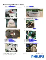
11. Assemble Rubber Support,
Trigger
5 and Trigger Spring
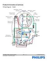
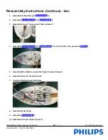
12. Dress wire according to wiring diagram below
13. Assemble
Iron LED Assy
2 to
MS LED Holder
3, assemble to
Housing Prted
4
14. Assemble Screw E, fasten Screw E
15. Connect wire (Micro Switch to Hose Cord)
16. Assemble
Inlay 2K Assy
1
17. Assemble Screw A, fasten Screw A
18. Assemble Screw B, Fasten Screw B
Cautions:
a. before fastening screw, relocate the screw with first thread. Once done fasten the screw.
b. Do not drop, hit or knock the ASO/ PCBA. (ESD wrist strap & proper pack with ESD bag)
c. Ensure there is click sound after Connector to Terminal engagement for wire connection.

