


GC7320
3-7
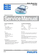
PARTS LIST - IRON & ELECTRICAL DIAGRAM
STAND
IRON
L
N
Boiler Electronics
Thermal
Fuse
Thermal
Fuse
Pump
Thermistor 1
L
N
L
S
N
M
Boiler
Heating
Element
Electro-
valve
Ther-
mostat
Trigger
Switch
Heating
Element
Fig 4 . Electrical diagram
Pos
Service code
Description
1
2
3
4
5
6
7
8
9
10
12
13
14
15
16
17
18
19
20
21
22
23
4239 026 30740
4239 026 30750
4239 021 41080
4239 021 47570
4239 026 08280
4239 026 30790
4239 021 46060
4239 026 01220
4239 021 42390
4239 010 10110
4239 026 30780
4239 014 54370
4239 021 47590
4239 026 30770
4239 021 47580
4239 026 30760
4239 015 70150
4239 026 13220
4239 015 56530
4239 010 09350
4239 010 10280
4239 021 41290
Backplate
Swivel
Hose cord assy
Inlay Non SOS assy
Lamp cover
Steam lock
Lamp assy
Lamp holder
Microswitch assy
Hose clip - Iron
Trigger
Trigger spring
Thermostat dial assy
Rattle spring
Housing printed
Soleplate cover
Ryton ring
Thermostat bush
Braided rubber hose - non SOS
Brass joint
Hose clip - braided rubber hose
Soleplate assy 230 V


