


1-10
Gamepor
t Operations
About Gamepor
t
Gamepor
t allo
ws y
ou to connect y
our game
console to this audio system which enab
les yo
u
to enjo
y a total game imme
rs
ion exper
ience
through pow
erful sound output.
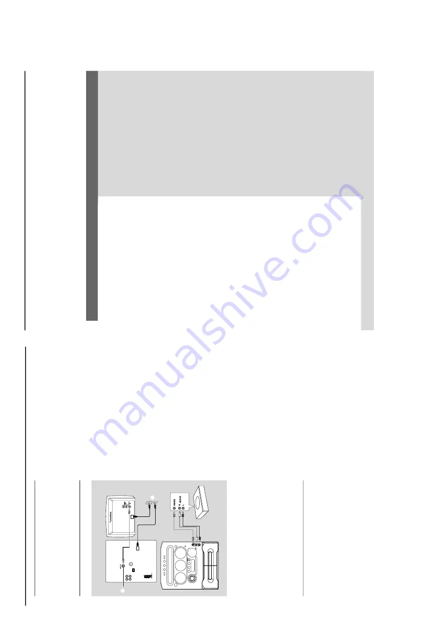
Pr
eparation before use
1
Connect y
our game console’
s video and audio
output to the GAMEPO
RT
video and audio
inputs respectiv
e
ly (refer to
“
Connections -
Connecting to game consol
e
).
2
Connect y
our
TV’
s video input to the
VIDEO
OUT
(
CVBS
) on the rear panel
.
3
Connect all the
A
C
po
wer cord to the po
we
r
outlet.
Star
ting operation
4
Tu
rn
on the
TV and set to the cor
rect video-in
channel.
The
TV’
s video input channel may be calle
d
A
UX(iliar
y) IN,
A
UDIO/VIDEO (A/V) IN,
EXT 1,
etc
.
These channels are often near channel 00
on y
our
TV
. Or
, y
our
TV remote control ma
y
ha
ve
a button or switch that chooses diff
erent
video modes.
See y
our
TV man
ual f
or details.
5
Press
A
UX•GAME
until
“
GAMEPORT
” i
s
displa
y.
6
Press
GAME
to select the type of sound setting
that best suit the game
:
SPEED
, PUNCH,
BLAST
or
OFF
.
7
If y
ou lik
e to mix your game sound to y
our
fa
vour
ite musi
c,
press
MIX-IT
to select the
desired music source
:
CD
,
TUNER
,
AU
X
,
T
APE
or
OFF
.
CD
™
“
MIX-CD
"
TUNER
™
“
MIX-TU
"
AU
X
™
“
MIX-AUX
"
T
APE
™
“
MIX-TA1
" /
“
MIX-TA2
"
OFF
™
“
MIX-OFF
"
Note:
–T
o c
hange the disc tr
ay
, you have to pr
ess CD
,
then press CD 1~3 to select the desir
ed disc tr
ay
.
8
If necessar
y, star
t playback of y
our chosen mix
e
r
source
.
9
Star
t pla
ying y
our fa
vour
ite game
.
To
adjust the game console’
s v
olume
le
v
e
l
Adjust
GAME V
O
LUME
.
Notes:
–Y
ou can only activate GAME
V
OLUME and MIX-
IT while in the game source mode
.
–I
f your game console is
sw
itc
hed on,
the video
image will alw
ays appear on the
TV e
ven though
you are not in the gamepor
t mode
.
Rear panel
Fr
ont panel
2
3
Game console
OUT
OUT
8
W
ARNING
Under no circumstances should you tr
y to r
epair the system your
self,
as this will in
validate the
w
arr
anty
. Do not open the system as ther
e is a risk of electric shock.
If a fault occur
s,
first check the points listed belo
w before taking the system for r
epair
. If you
are unable to remedy a pr
oblem b
y
follo
wing these hints
, consult your dealer or Philips for
help.
Radio reception is poor
.
“NO DISC” is displa
y
ed or the disc cannot
be pla
y
ed.
The system does not react when buttons ar
e
pr
essed.
Sound cannot be hear
d or is of poor quality
.
The remote contr
ol does not function
pr
operl
y.
The timer is not working.
The system displa
ys featur
es automaticall
y and
buttons star
t flashing.
If the signal is too w
eak,
adjust the antenna or connect
an exter
nal antenna f
o
r better reception.
Increase the distance betw
een the system and y
our TV
or
VCR.
Inser
t a disc
.
Load in the disc with the labeled side facing up
.
Replace or clean the disc
, see
“Care and saf
ety
info
rm
ation”.
Use a f
inalised CD-R(W) or a cor
rect for
m
at disc
.
Remo
ve and reconnect the
AC
pow
er cord and switch
on the system again.
Adjust the v
o
lume
.
Disconnect the headphones.
Check that the speak
er
s are connected cor
rectl
y.
Check that the
A
C
po
w
er cord is connected proper
ly
.
Select the source (CD or
TUNER,
f
o
r example) bef
ore
pressing the function b
utton (
ÉÅ
,
S
,
T
).
Reduce the distance betw
een the remote control and
the system.
Replace the batter
y.
Po
int the remote control directly to
ward the IR sensor
.
Set the clock cor
rectly
.
Press
TIMER ON/OFF to switch on the time
r.
Press and hold DEMO ST
OP on the main unit to switch
off the demonstr
ation mode
.
Pr
ob
lem
Solution
Tr
oub
leshooting
Refer to the
FA
Q (Frequently
Ask
e
d Questions) on the supplied CD-ROM or visit our w
ebsite
“www
.audio
.philips.com”
f
o
r latest update on
FA
Q
.
Summary of Contents for FWM570/21
Page 11: ...2 1 2 1 Figure 1 Figure 2 Figure 4 Figure 3 Figure 5 Figure 6 ...
Page 14: ...Service position A Service position B Service position C 2 4 2 4 DISMANTLING INSTRUCTIONS ...
Page 20: ...5 2 5 2 CONTROL BOARD COMPONENT LAYOUT ...
Page 21: ...5 3 5 3 CONTROL BOARD CHIP LAYOUT ...
Page 26: ...6 2 6 2 DISPLAY BOARD COMPONENT LAYOUT ...
Page 27: ...6 3 6 3 DISPLAY BOARD CHIP LAYOUT ...
Page 71: ...10 4 Wiring Disc Motor Inner switch Slide Motor Service Position ...
Page 84: ...11 2 11 2 AF12 BOARD COMPONENT LAYOUT ...
Page 85: ...11 3 11 3 AF12 BOARD CHIP LAYOUT MAPPING AF12 BOARD COMPONENT LAYOUT MAPPING ...


