CIRCUIT DIAGRAM - AC BOARD
7-1
7-1
-32V
GND
GND
+32V
0V
127V
0V
14V
127V
110V
220V
ONLY FOR ECO FWM452/12
ONLY FOR ECO FWM452/55
D801
1N41481
Q802
8050
Z802
9V1
R822
1K5
C835
220uF
R821
47R 1/2W
M
C802
104
M
C828
104
+
C806
3300UF/50V
+
C821
3300UF/50V
F805
T5A L 250V
AC
230V/50Hz
F806
T2A L 250V
1
2
3
4
CON801
F804
T5A L 250V
T801
F802
T3.
15A
L 250V
1
2
3
4
5
6
SW801
NTC
D848
1N4001
F807
T200mAL 250V
+
C810
47UF
R835
R834
1k
R833
10R
1/6W
Q801
8050D
+ C808
10V
100U
U801
LM1117-3.3V
D805
1N4001
M
C811
104
+
C807
10V
100U
M
C825 0.02U
M
C823 0.02U
M
C824 0.02U
M
C822 0.02U
D824 1N4001
D822 1N4001
D823
1N4001
RL801
DC6V
D821
1N4001
T802
EI28
M
C827 0.02U
M
C804 0.02U
M
C826 0.02U
M
C803
0.02U
D818 1N5402
D816
1N5402
D817
1N5402
D815
1N5402
M
C833 0.02U
M
C834 0.02U
M
C832 0.02U
M
C831 0.02U
D833 1N5392
D834 1N5392
D832 1N5392
D831
1N5392
1
2
3
4
5
6
CON802
M
C843
104
+
C801
4700UF/25V
R836
10K
R80110K
D835
1N5392
M
C809
104
R810110k
NTC
3V3
+14V
NTC
ECO
All manuals and user guides at all-guides.com
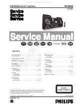
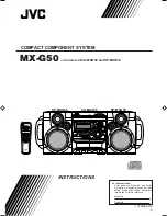
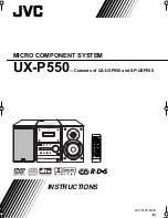
Summary of Contents for FWM462
Page 12: ...LAYOUT DIAGRAM MAIN BOARD TOP SIDE 6 2 6 2 All manuals and user guides at all guides com ...
Page 13: ...LAYOUT DIAGRAM MAIN BOARD BOTTOM SIDE 6 3 6 3 All manuals and user guides at all guides com ...
Page 15: ...PCB LAYOUT AC BOARD 7 2 7 2 All manuals and user guides at all guides com ...
Page 17: ...LAYOUT DIAGRAM DISPLAY BOARD TOP SIDE 8 2 8 2 All manuals and user guides at all guides com ...
Page 20: ...PCB LAYOUT AMP BOARD TOP SIDE 9 2 9 2 All manuals and user guides at all guides com ...
Page 22: ...CIRCUIT DIAGRAM TUNER BOARD 10 1 10 1 All manuals and user guides at all guides com ...
Page 23: ...LAYOUT DIAGRAM TUNER BOARD 10 2 10 2 All manuals and user guides at all guides com ...
Page 24: ...CIRCUIT DIAGRAM CD BOARD 11 1 11 1 All manuals and user guides at all guides com ...
Page 25: ...LAYOUT DIAGRAM CD BOARD TOP SIDE 11 2 11 2 All manuals and user guides at all guides com ...
Page 29: ...PCB LAYOUT MCU BOARD TOP SIDE 12 3 12 3 All manuals and user guides at all guides com ...
Page 30: ...PCB LAYOUT MCU BOARD BOTTOM SIDE 12 4 12 4 All manuals and user guides at all guides com ...


