Service Modes, Error Codes, and Fault Finding
EN 20
FHP PDP
5.
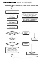
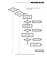
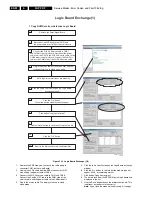
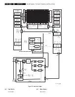
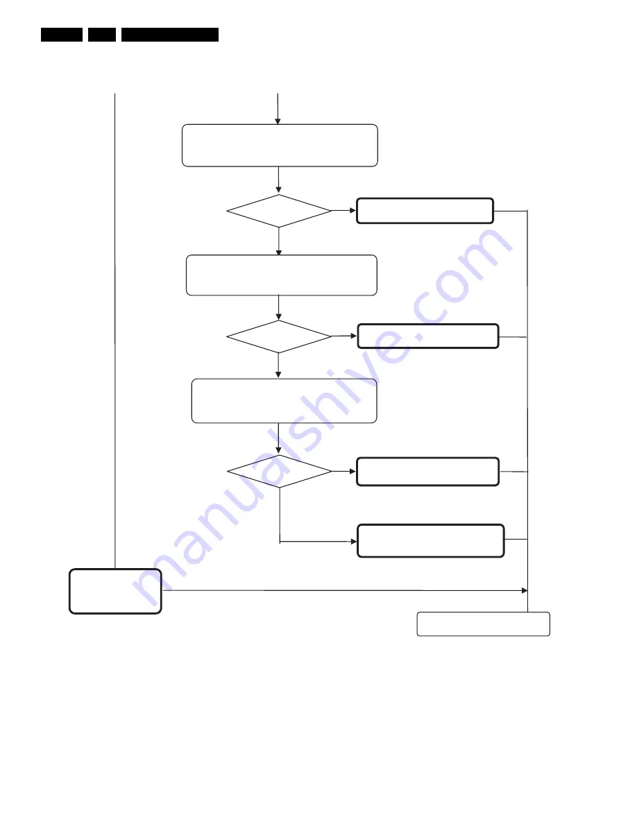
Figure 5-11 Vertical line / vertical bar problem analysis procedure (3/3)
Y
Normal?
ABUS-R board is defective
N
Turn “OFF” the main power
Replace LOGIC board
Normal?
LOGIC board is defective
Y
Turn “OFF” the main power
Replace signal cables LOGIC - ABUS-R
N
Panel is defective
(PDP is defective)
Replace the defective parts
Normal?
Y
Signal cable is defective
ADM is defective
(PDP is defective)
N
(2)
(3)
Turn “OFF” the main power
Replace ABUS-R board
G_16400_032.eps
310706
*
1
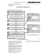
When turning “ON” the PDP with PDP-go, refer to following procedure:
1. Connect the special LVDS cable (see paragraph “Repair Tools”)
2. Supply power to the PSU
between CN01 and CN06
Give the “PDP-go” signal (*1)
Give the “PDP-go” signal (*1)
Give the “PDP-go” signal (*1)

