2
How to remove the CD manually from the tray
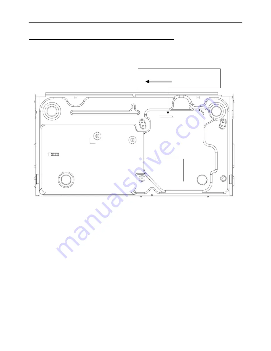
1. Please do as below instruction in case the tray can not be open:
a. Power off the DVD player.
b. Please gently push the guider and wait until the tray comes out(Figure1).
use jig move this part left
Page 1: ...n List 10 Service Manual Copyright 2011 Philips Consumer Electronics B V Eindhoven The Netherlands All rights reserved No part of this publication may be reproduced stored in aretrieval system or transmitted in any form or by any means electronic mechanical photocopying or otherwise without the prior permission of Philips Published by by MTC LX 1111 AV System Printed in The Netherlands Subject to ...
Page 2: ... CD manually from the tray 1 Please do as below instruction in case the tray can not be open a Power off the DVD player b Please gently push the guider and wait until the tray comes out Figure1 use jig move this part left ...
Page 3: ...go should be on the screen and the witch will display Insert the AC power line over again NG OK NG PSU Fail The LED module Fail Press the standby button to power on the set The Philips logo should be on the screen and the witch will display NG The DSP Fail Replace Mainboard PCBA Replace frontboard PCBA TEST 1 2V and 3 3V Power NG OK Replace flash U11 NG Replace Q5 Q6 NG ...
Page 4: ...Audio output Connect the AV OK Power on the set Play the disc and the audio will output from the TV OK NG Adjust the volume to add the volume from the TV Test Finish NG The Audio DA Fail or the DSP Fail Replace Mainboard PCBA ...
Page 5: ...put when DVD CD PLAY play the KARAOKE disc and then set the menu of setup and to set the kalaok to on Sing with MICROPHONE and the audio will output from the TV OK NG check the MICROPHONE is on Test Finish NG The Karaoke board is broken Replace The Karaoke board PCBA ...
Page 6: ...he disc and on the screen display the Loading OSD NG NG The servo chip or DSP chip fail Replace LOADER and check again The disc s info will display the screen NG Note to hear the playback sound when close the tray door to playing the disc NG NG The loader or servo chip or DSP chip fail NG Replace Mainboard PCBA Please power off then power on the set to playback the disc over again ...
Page 7: ...ay the firmware CD disc and the upgrade menu will appear 4 First Select PLAY button and start to automatically upgrade on the first upgrade menu 5 Then the upgrade process will start and appear Upgrading please don t power off during this state 6 During the updating the tray door is openning when the update is complted the unit will power off and then re start automatically to close the tray door ...
Page 8: ...First press SETUP key on the RC in Preferences menu can see the option of Audio Then press Right key to select Audio or subtitle language which you want 3 How to change the DVD region code First press SETUP key on the RC in Preferences menu Then press 138931 key to enter the DVD region code setting menu it will appear region code 3 and press UP or DOWN key to set the region code Note 1 means 1 reg...
Page 9: ...V USB READER OPTION G Y U SY TO FRONTBOARD DSP MT1389J COXAIL OUT UART IPOD_RX IPOD_TX P 12V P 5V 3 3V 1 2V TO LOADER FLASH EN25F16 SPI 4558 MOTO DRIVER CD5888 AUDIO R L OUT USB_DM USB_DP 4M 16 SDRAM RCA JACK 2CH RCA JACK L R CH BLOCK DIAGRAM 9 1 9 1 ...
Page 10: ...OP NJM4558 DSP MT1389D TO LOADER OPU 24P FFC WIRE 16M FLASH 3 3V ADJ 1 2V ADJ MOTOR DRIVER TO FRONT BOARD IR_IN STB_KEY PLAY PAUSE_KEY OPEN CLOSE_KEY 5V GND AC IN FUSE TO LOADER LOAD LOAD TROUT GND TRIN SL SL GND TROUT SP SP A 卡 拉 OK WIRING DIAGRAM 9 2 9 2 ...
Page 11: ...60 DIO SR360 2 1 PD6 1N4007 DIO 214AC PD6 1N4007 DIO 214AC 2 1 PR3 10Ω RC0805 PR3 10Ω RC0805 PR10 5 1KΩ RC0402 PR10 5 1KΩ RC0402 PC208 102 100V CAP 5 7 5X2 5 PC208 102 100V CAP 5 7 5X2 5 PC2 1uF 25V CC0805 PC2 1uF 25V CC0805 PD103 TL431 PD103 TL431 1 3 2 T101 ZY T0103 TRAN10 EE199 4X13 T101 ZY T0103 TRAN10 EE199 4X13 2 3 5 4 7 9 6 8 PEC2 100uF 25V EC2DT2 5X8X5V PEC2 100uF 25V EC2DT2 5X8X5V PCON2 C...
Page 12: ...N78 33Ω 4 U11 EN25F16 U11 EN25F16 CS 1 DO 2 WP 3 VSS 4 VCC 8 HOLD 7 CLK 6 DIO 5 1 GND 2 D 3 D 4 VCC 4 2 3 1 P4 4pin 2 0mm 1 GND 2 D 3 D 4 VCC 4 2 3 1 P4 4pin 2 0mm 3 2 1 4 5 6 R36 10KΩ R36 10KΩ 1 2 R175 0Ω R175 0Ω 1 2 C24 0 1uF 25V C24 0 1uF 25V R35 10KΩ R35 10KΩ 1 2 R38 10KΩ RC0402 R38 10KΩ RC0402 PR222 0Ω PR222 0Ω 1 2 TF1 FLASH auto test FLTP TF1 FLASH auto test FLTP 1 2 3 4 5 7 8 6 F1 42Ω 4A LC...
Page 13: ...8 4 13D 1 1 2 2 3 3 4 4 5 5 6 6 R119 75Ω R119 75Ω 1 2 L14 0Ω L14 0Ω 1 2 C53 100PF 50V C53 100PF 50V 1 2 C51 100PF 50V C51 100PF 50V 1 2 L12 600Ω 150mA L12 600Ω 150mA 1 2 C47 100PF 50V C47 100PF 50V 1 2 FB65 SBY100505T 121Y N FB65 SBY100505T 121Y N CB61 100PF 50V CB61 100PF 50V L13 0Ω L13 0Ω 1 2 FB64 SBY100505T 121Y N FB64 SBY100505T 121Y N C52 100pF NC C52 100pF NC 1 2 R117 nc 100 1 R117 nc 100 1 ...
Page 14: ...4 SOT23 1 2 3 R73 30KΩ R73 30KΩ C40 0 1uF 25V C40 0 1uF 25V Q15 2N3906 Q15 2N3906 1 2 3 FB60 NC FB 600R 0402 FB60 NC FB 600R 0402 R74 10KΩ R74 10KΩ R65 NC 100k R65 NC 100k R75 5 1KΩ R75 5 1KΩ C32 NC 1000pF C32 NC 1000pF R84 100Ω R84 100Ω R83 330Ω R83 330Ω C27 NC 1000pF C27 NC 1000pF J10 CON5 2 00mm J10 CON5 2 00mm 1 2 3 4 5 CE33 47uF 16v CE33 47uF 16v 1 2 CE24 NC 10uF 16v CE24 NC 10uF 16v 1 2 C38 ...
Page 15: ...Ω R32 10KΩ R34 33Ω R34 33Ω Q6 8550C TO92 Q6 8550C TO92 1 2 3 C23 0 1uF 25V C23 0 1uF 25V U2 NC M12L16161A 6 U2 NC M12L16161A 6 VCC 1 DQ0 2 DQ1 3 VSSQ 4 DQ2 5 DQ3 6 VCCQ 7 DQ4 8 DQ5 9 VSSQ 10 DQ6 11 DQ7 12 VCCQ 13 DQML 14 WE 15 CAS 16 RAS 17 CS 18 BA A11 19 A10 20 A0 21 A1 22 A2 23 A3 24 VCC 25 VSS 26 A4 27 A5 28 A6 29 A7 30 A8 31 A9 32 NC 33 CKE 34 CLK 35 DQMH 36 NC 37 VCCQ 38 DQ8 39 DQ9 40 VSSQ 4...
Page 16: ... CB49 100PF 50V R16 33Ω R16 33Ω CB5 0 1uF 25V CB5 0 1uF 25V BC38 0 1uF 25V BC38 0 1uF 25V L5 120Ω 500mA L5 120Ω 500mA CB15 0 1uF 25V CB15 0 1uF 25V R20 4 7Ω R20 4 7Ω C8 33PF 50V C8 33PF 50V R25 15KΩ R25 15KΩ CB4 0 1uF 25V CB4 0 1uF 25V R10 100KΩ R10 100KΩ CB48 100PF 50V CB48 100PF 50V C2 0 1uF 25V C2 0 1uF 25V R14 0Ω R14 0Ω TP4 TP4 J3 NC 4P 2 0 J3 NC 4P 2 0 1 2 3 4 U10 NC 24C02 U10 NC 24C02 A0 1 A...
Page 17: ...PCBA LAYOUT DIAGRAM COMPONENT SIDE VIEW 9 9 ...
Page 18: ...PCBA LAYOUT DIAGRAM COPPER SIDE VIEW 9 10 ...
Page 19: ...11 12 5 7 6 2 3 KARAOKE PCBA FRONT PANEL PCBA BUTTON PCBA MAIN PCBA EXPLODED VIEW DIAGRAM 9 11 9 11 ...
Page 20: ...10 Revision List Version 1 0 initial Release ...