EN 15
3139 785 31510
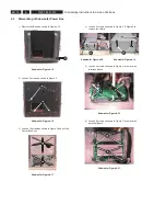
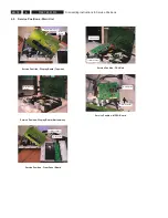
7) Loosen 2 screws to remove the MPEG Board.
Figure 4-7
Note: Please change from Ground Point A to Ground Point B
to achieve Service Position for Display Board.
Figure 4-8
Figure 4-9
Figure 4-10
7
7
Dismantling Instructions & Service Positions
4.
GND POINT A
GND POINT B
4.2 Dismantling of the Wireless Box Surround
1) Loosen 4 screws to remove the Cover for the Wireless
Box Surround.
Figure 4-11
2) Loose 4 screws each to remove the Amplifier Board.
Figure 4-12
3) Loose 4 screws to remove the Wireless Receiver
Figure 4-13
4) Loosen 4 screws to remove the PSU Module.
Figure 4-14
1
1
2
2
GND POINT B
GND POINT A
3
3
4
4

