Disassembly Diagram
4-1
4-1
A. Loose these Claspers to remove
the DVD Door
C. Loose 4pcs screws (3 x 5 BMTT) to
B. Remove the Top Cover
remove the Blu-Ray Loader Driver
Mechanism Cover
C
E. Loose 4pcs screws (3 x 16 BMTT) to
remove the Power Board
D. Loose 4pcs screws(3 x 8 BMTT) to
remove the Blu-Ray Loader Driver
Mechanism
I. Remove the Decoder Board(Main Board)
F2
F3
G
D
E
H. Remove the HDMI Board(Scalar Board)
G. Loose 2pcs screws(3 x 5 BMTT) to
remove the Power Transmit Board
F. Remove the Output Board(Audio
Board)
F2. Loose 2pcs screws(3 x 6 BM)
F1. Loose 4pcs screws(3 x 15 BM) to remove
the Fans
H2. Loose 2pcs screws(3 x 5 BMTT/silver)
H3. Loose 2pcs screws(3 x 8 BA)
H1. Loose 3pcs screws(3 x 5 BMTT)
E2. Loose 4pcs screws(3 x 5 KMTT)
B1. Loose 2pcs screws(3 x 8 KA)
F3. Loose 3pcs screws(3 x 10 BA)
J. Loose 2pcs screws(3 x 5 BMTT) to
remove Front Cabinet
K. Loose 2pcs screws(2.6 x 8 BT) to
remove the Display Board
L. Loose 3pcs screws(2.6 x 8 BT) to
remove the MCU Board
I1. Loose 2pcs screws(3 x 10 BA)
I2. Loose 2pcs screws(3 x 8 BA)
F1
B1
B2
H1
H3
H2
I1
I2
F1
G
G
Summary of Contents for BDP9500
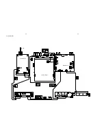
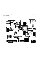
Page 16: ...7 2 7 2 MCU Board Layout Diagram ...
Page 18: ...8 2 8 2 VFD Display Board Layout Diagram ...
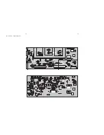
Page 22: ...11 2 11 2 Output Board Audio Layout Diagram ...
Page 24: ...12 2 12 2 Power Board Layout Diagram ...
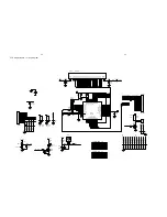
Page 32: ...13 8 13 8 HDMI Board Scalar Layout Diagram ...
Page 42: ...14 10 14 10 Decoder Board Layout Diagram ...
Page 43: ...15 1 15 1 Exploded View ...


