Philips BDP2930 /12 Service Manual Download Page 12

5

5

4

4

3

3

2

2

1

1

D

D

C

C

B

B

A

A

GN

D

POWER

IR

B6

B1

B4
B5

A1
A2
A3
A4
A5
A6
A7

B2
B3

CLK
STB

DATA

U

SBP0

U

SBM

0

A1
A2
A3
A4
A5
A6
A7
B1
B2
B3
B4
B5
B6

IR
POWER

GND
GND

GND

USB-VCC

GND

USBM0
USBP0

OPEN/CLOSE

STB
DATA

DATA

+12V

CLK

VCC
VCC

+12V

USBM0

USBP0

USB-VCC

OPEN/CLOSE

VCC

VCC

VCC

VCC

+12v

D1

D1

D1

D1

PJ1

16PIN

DIP2.0-14BDP

PJ1

16PIN

DIP2.0-14BDP

1

2

3

4

5

6

7

8

9

10

11

12

13

14

15

16

17

18

19

PJ4

13PA-2.54MM

PJ4

13PA-2.54MM

1
2
3
4
5
6
7
8
9

10
11
12
13
14
15
16

+

PC15

220uF/10V

+

PC15

220uF/10V

1

2

PK1

POWER

PK1

POWER

1

2
4

3

+

PC12

100uF/10V

+

PC12

100uF/10V

1

2

PJ2

13PA-2.0MM

PJ2

13PA-2.0MM

1
2
3
4
5
6
7
8
9

10
11
12
13
14
15
16

+

PC16

100uF

/10V

+

PC16

100uF

/10V

1

2

PU4

SM1628

PU4

SM1628

INT

1

Seg2/Ks2

9

Seg3/Ks3

10

Seg5/Ks5

12

CLK

3

DI/O

2

Seg8/Ks8

15

Vdd

7

Seg7/Ks7

14

Seg6/Ks6

13

VDD

21

Seg13/Grid6

19

Seg14/Grid5

20

Grid3

24

Grid1

27

KEY2

6

STB

4

KEY1

5

GND

28

Seg1/KS1

8

Seg4/Ks4

11

Seg10/Ks10

17

Seg12/Grid7

18

Seg9/Ks9

16

Grid4

23

GND

22

GND

25

Grid2

26

PR19
10K

PR19
10K

IR1

IR_MS-C2FN61NL

IR1

IR_MS-C2FN61NL

DE

T

1

GN

D

2

VC

C

3

PR20

100R

PR20

100R

1:GND

2:D+

3:D-

4:VCC

4

2

3

1

PJ6

USB/DIP
USB-SERIES-4PA

1:GND

2:D+

3:D-

4:VCC

4

2

3

1

PJ6

USB/DIP
USB-SERIES-4PA

2

3

4

1

5

6

8

7

PR21
10K

PR21
10K

D2

D2

D2

D2

PK2

OPEN/CLOSE

PK2

OPEN/CLOSE

1

2
4

3

R4

0R/0805

R4

0R/0805

PR27

0R/0805

PR27

0R/0805

PR18
10K

PR18
10K

PR22
51K

PR22
51K

PC14
100pF

PC14
100pF

PR25

0R/0805

PR25

0R/0805

PC18

0.1uF

PC18

0.1uF

5-3

6-2

Summary of Contents for BDP2930 /12

Page 1: ... otherwise without the prior permission of Philips Blu ray Disc Player Version 1 0Version 0 0 Published BG AVM Printed in The Netherlands Subject to modification TABLE OF CONTENTS Chapter Technical Specification PCBs Location 1 Safety Instruction 2 Instruction for Use 3 Mechanical and Dismantling Instructions 4 Service Modes Troubleshooting 5 Overall Block Diagram Wiring Diagram 6 Electrical Diagr...

Page 2: ...kpbs 192 kpbs USB Compatibility Hi Speed USB 2 0 Class support USB Mass Storage Class File system FAT16 FAT32 Support HDD a portable hard drive disc an external power source may be needed Main unit Power supply rating AC 110 127V 50Hz 60Hz Power consumption 11 W Power consumption in standby mode 1 W Dimensions w x h x d 310 X 40 X 203 mm Net Weight 1 1 kg Accessories supplied Remote control and 2 ...

Page 3: ...1 1 PCBs Location VERSION VARIATIONS Type Versions Service policy Board in used BDP2930 TIPS C Component Lever Repair M Module Lever Repair X OCX 1 2 M 12 PSU PCBA MAIN BOARD M PSU PCBA MAIN BOARD ...

Page 4: ...e the Main board will be Cancel Start damaged entirely 4 Press Right cursor button to choose Start then press OK 5 The software will updagrde and screen will display as below Upgrade is ongoing Please wait Please do not unplug or switch off the device 6 Restart the set B Update software via USB Flash Drive 1 Go to www philips com support to check if the latest software version is available for thi...

Page 5: ...ord and connect a wire between The two pins of the mains plug 2 Set the mains switch the on position keep the Mains cord unplug 3 Measure the resistance value between the mains plug and the front panel controls and chassis bottom 4 Repair or correct unit when the resistance measurement is less than 1M Ω 5 Verify this before you return the unit to the customer user ref UL standard no 1492 6 Switch ...

Page 6: ...3 0 Instruction for Use You can download this information from the following websites http www philips com support http www p4c philips com 3 1 ...

Page 7: ...hen remove the Top Cover 4 1 Step3 Remove the 9 screws on board to dismantle the DVD BOARD PSU BOARD DECK Step2 Dismantling Front Panel the CD door should be removed first then gently pull the Panel out from the set PS insert reset hole once the disc tray jammed use an acuate press the reset hole to release the disc tray remove the door from the tray ...

Page 8: ...t Correct connection Replace PU4 or LED DISPLAY Yes Go Yes No Check 5V 12V voltage on the power board DATA CLK STB on the power board 1 Check whether bad solder exists on PU4 and pins of LED DISPLAY 2 Check whether the circuit connected to PK1 PK2 is broken Fix the power board Trouble shooting chart 5 1 Check the signals of the PU4 s Check the PU4 power supply PU4 7 5V and PU4 21 5V ...

Page 9: ...the battery for remote controller Check whether the remote controller s battery is exhausted or not Check the Power supply board part Replace IR1 NO Trouble shooting chart 5 2 Check the IR1 power supply is OK Check whether bad solder exits on IR1 pins Yes Fix the connection NO Yes ...

Page 10: ...er Board Can t read disc or can t open the disk door Check 40pin and 8pin cable from main board connection to the loader is normal Check the U409 and the peripheral components near them on the main board NO GO Check whether the DVD loader running is normal Fix the connection NO Yes Trouble shooting chart 5 3 ...

Page 11: ...71 PRV1 TVR10471 PC5 1nF PC5 1nF PCY1 2 2nF PCY1 2 2nF PC13 10uF 50V PC13 10uF 50V PR9 470 0805 PR9 470 0805 PT1 EE19 PT1 EE19 2 1 3 4 5 6 7 8 PD5 FR107 PD5 FR107 PC2 222 1KV PC2 222 1KV PR12 10K PR12 10K PZD2 15V 0 5W PZD2 15V 0 5W PR10 2 2K 0805 PR10 2 2K 0805 PR2 100R 5 PR2 100R 5 PC6 1000uF 10V PC6 1000uF 10V PR5 10R 0805 PR5 10R 0805 PR4 10K PR4 10K PD2 1N4007 PD2 1N4007 PD9 SR2100 PD9 SR2100...

Page 12: ...5 6 7 8 9 10 11 12 13 14 15 16 PC16 100uF 10V PC16 100uF 10V 1 2 PU4 SM1628 PU4 SM1628 INT 1 Seg2 Ks2 9 Seg3 Ks3 10 Seg5 Ks5 12 CLK 3 DI O 2 Seg8 Ks8 15 Vdd 7 Seg7 Ks7 14 Seg6 Ks6 13 VDD 21 Seg13 Grid6 19 Seg14 Grid5 20 Grid3 24 Grid1 27 KEY2 6 STB 4 KEY1 5 GND 28 Seg1 KS1 8 Seg4 Ks4 11 Seg10 Ks10 17 Seg12 Grid7 18 Seg9 Ks9 16 Grid4 23 GND 22 GND 25 Grid2 26 PR19 10K PR19 10K IR1 IR_MS C2FN61NL IR...

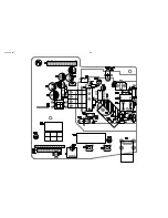
Page 13: ...Main PCB TOP 6 3 ...

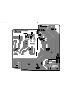
Page 14: ...Main PCB Bottom 6 4 ...

Page 15: ...PSU PCB TOP 6 5 ...

Page 16: ...PSU PCB BOTTOM 6 6 ...

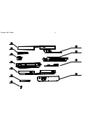
Page 17: ...Exploded View Diagram 7 1 ...

Page 18: ...9 0 REVISION LIST Version 1 0 x Initial release ...

Reviews: