Philips BDH5011 User Manual Download Page 36

10.5  Variable and Fixed Audio
Output

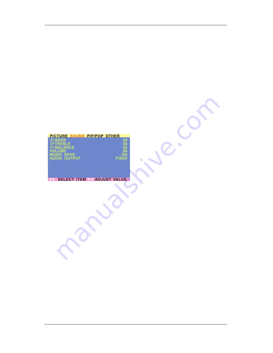
Setting Output Using OSD

You can set the type of output this display
outputs from its audio output jack located in the
rear of the display. By using an OSD based
switch, you can easily choose between variable
or fixed audio outputs.

To set the audio output setting:

1. Press the MENU 

+/-

keys on the remote or

the front control panel.

2. Use the ADJ 

+/-

keys to navigate to SOUND

OSD sub-menu.

3. Use the MENU 

+/-

keys to select the

AUDIO OUTPUT option.

4. Use the ADJ 

+/-

keys to change setting

between FIXED or VARIABLE.

AUDIO OUTPUT

Sets the type of audio output sent from the
audio output jacks located in the rear of display.

VARIABLE

When set to Variable, audio output is
affected by the display’ sinternal audio
controls including bass, treble, surround, BBE,
bass extension, and volume.

FIXED

When set to Fixed, the audio output
bypasses the display’s internal audio control
so that functions such as bass, treble,
surround, BBE, bass extension, and volume
controls have no effect.

10.6  Sound Adjustments

Sound Adjustments Using OSD

Sound adjustments are available to enhance the
sound performance of the display.These
adjustments will affect the display’s built-in
speakers and the AUDIO OUTPUT jacks when
set to ‘Variablel’ (see above section).To access
sound adjustments:
1. Press the MENU 

+/-

keys on the remote or

the front control panel.

2. Use the ADJ 

+/-

keys to navigate to SOUND

OSD sub-menu.

3. Use the MENU 

+/-

keys to select the various

options described in this section.

36

User Manual BDH5011

Summary of Contents for BDH5011

Page 1: ...User Manual Benützersanleitung Guida Utente Manual de uso Manuel de l utilisateur TYPE NR BDH5011 Philips Business Solutions G I S F E ...

Page 2: ...cting Signal Source 24 8 3 Adjusting Sound Volume 25 9 USING WITH HDTV 26 9 1 Understanding HDTV 26 10 ADVANCED FUNCTIONS 28 10 1 Picture In Picture PIP Side by Side Picture POP 28 10 2 Widescreen 16 9 Aspect Ratio Viewing Modes 32 10 3 On Screen Display OSD Settings 34 10 4 Sleep Timer Settings 35 10 5 Variable and Fixed Audio Output 36 10 6 Sound Adjustments 36 10 7 Inner Speaker ON OFF 37 10 8 ...

Page 3: ...el only Keep display away from excessive dust high temperatures moisture or direct sunlight Use in a well ventilated area and do not cover ventilation openings Unauthorized modification of this equipment or usage of an unshielded connecting cable may cause excessive interference When the display is not in use for a long period of time disconnect it from the electric outlet If the picture displayed...

Page 4: ...rload wall outlets and extension cords as this can result in a risk of fire or electric shock Disconnect the unit from the main supply and refer servicing to qualified service personnel under the following conditions Power cord or plug is damaged or frayed Liquid has been spilled into the product Unit has been exposed to water or moisture Unit does not operate normally when the operating instructi...

Page 5: ...eorient or relocate the receiving antenna Increase the separation between the equipment and the receiver Connect the equipment into an outlet on a circuit different from that to which the receiver is connected Consult the dealer or an experienced radio TV technician for help Operation of this equipment in a residential area is likely to cause harmful interference in which case the user will be req...

Page 6: ...lly treated Wipe the surface gently using only a cleaning cloth or a soft lint free cloth If the surface is particularly dirty soak a soft lint free cloth in a mild detergent solution Wring the cloth to remove excess liquid Wipe the surface of the display to remove dirt Then use a dry cloth of the same type to dry Do not scratch or hit the surface of the panel with fingers or hard objects of any k...

Page 7: ...on the plasma display Examples of still images may include still computer images still video game images still logos or pictures text and images displayed in 4 3 Normal mode Contents of this manual is subject to change without notice Trademark Credits VGA is a trademark of IBM Corporation Macintosh is a registered trademark of Apple Computer Corporation SVGA is a registered trademark of the Video ...

Page 8: ...l automatically synchronize the display to match the incoming signal source without manual intervention Picture in Picture PIP Watch two programs simultaneously using the display s picture in picture with four selectable window position settings Side by Side Picture POP Watch two programs simultaneous by splitting the screen in half HDTV Signal Compatible This display is capable of accepting 1080i...

Page 9: ...and digitally map the signals to fit within 1366 x 768 pixels Discrete Power ON OFF Separate Power ON OFF buttons on the remote control facilitates the recording of IR macros with advanced system setups Direct Input Selection Keys Separate input selection keys on the remote control allows quick and easy selection of various inputs RS 232 Serial Connection The RS 232 command set includes front pane...

Page 10: ...Supplied Accessories Please verify that you received the following items with your package content Plasma Display Remote Control User Manual Power Cable 5 Package Contents 10 User Manual BDH5011 ...

Page 11: ...ies The following accessories are available and may be purchased from your local sales representative Wall Mount Composite Video Cable RCA S Video Cable Mini Din Component Video Cable RCA to RCA Audio Cable RCA Cable 11 User Manual BDH5011 ...

Page 12: ...w color if the display is shut off but the main power cord is plugged into the back of the unit Solid Green Power ON Input Button Use this button to switch between available inputs Menu Buttons Use this menu to engage the On Screen Display menu Volume Adjustment Buttons Use these buttons to adjust volume up and down These keys also serve as adjustment keys when On Screen Display is engaged 6 2 Rea...

Page 13: ...e PIP or POP sub window See Chapter 10 7 Closed Captioning This key is not applicable to this monitor 8 V Chip These keys are not applicable to this monitor 9 MTS Stereo This key is not applicable to this monitor 10 Channel Lock Fav Set These keys are not applicable to this monitor 11 Sleep Timer Engages Sleep Timer Settings See Page 21 12 Discrete Power ON OFF Press OFF to send display into Stand...

Page 14: ... Scroll thru the major OSD category using or key 3 Press the or keys again to select sub options within the category 4 Press the or keys to change the actual sub option setting 21 Recall Recalls the default picture settings See Chapter 11 22 Display Press to show the status of the display 23 Wide Toggles between various aspect ratio settings See Chapter 10 PIP AV1 AV2 COMPONENT 1 1080I RGB M 06 AV...

Page 15: ...PR1 CR1 connec tor Note There are two sets of component inputs provided You can use either set of component inputs to connect your DVD Using S Video Input 1 Connect the S Video 4 pin DIN connector from the DVD to the S VIDEO input on the back of display 2 Connect the red R and white L audio jacks from the DVD to the R and L audio in jacks located next to the S VIDEO connec tor Using Composite AV V...

Page 16: ...n use either set of component inputs to connect your HDTV Set top box Using RGB Input 1 Connect the 15 pin D Sub RGB connector from the back of the HDTV Set top box to the RGB IN connector located on the back of the display 2 Connect the red R and white L audio out jacks from the HDTV Set top box to the R and L audio in jacks located to the left of the S VIDEO connector Note Some HDTV Set top boxe...

Page 17: ...plug for remote turn on applications that will auto matically send a remote turn on off signal to the external amplified speakers 2 Connect the red R and white L AUDIO OUT jacks from right side of the connector panel to the external amplified speaker 3 As an option you may use the remote turn on plug Please note that not all external amplified speakers can accept remote turn on signals Connecting ...

Page 18: ...subwoofer Notes The AUDIO OUT RCA jacks can be set to either Fixed or Variable audio output levels Please see Chapter 10 for additional explanation of this feature The RCA subwoofer outputs frequencies below 120Hz The subwoofer will use the same Fixed or Variable audio output setting as AUDIO OUT RCA jacks The 3 5mm phono earphone output level is always used for remote turn on off applications 18 ...

Page 19: ...cks to the R and L jacks located to the left of the VIDEO 1 connector Notes Your PC may have audio jacks in the form of a 3 5mm phono plug If this is the case you will need to use a phono plug to RCA converter cable in order to connect audio A RGB loop out labeled iaRGB OutlB will allow another RGB display to be connected The RGB loop out will display the same signal as the RGB In signal source Th...

Page 20: ...nal pin layout are as follows Pin 1 Received Line Signal Detector Data Carrier Detect Pin 2 Received Data RXD Pin 3 Transmit Data TXD Pin 4 Data Terminal Ready DTR Pin 5 Signal Ground Pin 6 Data Set Ready DSR Pin 7 Request To Send RTS Pin 8 Clear To Send CTS Pin 9 Ring Indicator Basic Format for Command Parameters In order to transmit data from the computer to the display the data must be sent in ...

Page 21: ...lay using RS 232 Item Cmd Data Details Read 80 81 A7 Reads the displays current settings for command 81 thru A7 Volume 81 01 64H Set between 01 64H Power On Off 83 00 01 00 Off 01 On Brightness 85 01 64H Contrast 86 01 64H V Size 87 01 64H V Position 88 01 64H H Size 89 01 64H H Position 8A 01 64H Color 8E 01 64H Tint 8F 01 64H Sharpness 90 01 64H Input Select 91 00 07 00 TV 01 AV1 02 AV2 03 AV3 0...

Page 22: ...RF Input A0 00 01 00 Air 01 Cable Full Search A1 00 00 initiate full search MTS A4 00 02 00 Stereo 01 Mono 02 SAP Zoom A5 00 05 00 16 9 01 Panorama 02 4 3 03 Zoom1 04 Zoom 2 05 Zoom3 PIP POP A7 00 03 00 Normal 01 PIP 02 POP1 03 POP2 4 3 04 POP3 16 9 22 User Manual BDH5011 ...

Page 23: ...ntrol once again Using Discrete Power ON OFF Keys 1 The discrete POWER ON OFF keys sends two discrete signals to the display 2 To turn power on simply press the POWER ON button If the display is turned on already pressing this button will have no effect 3 To turn off power simply press the POWER OFF button If the display is already turned off pressing this button will have no effect POWER Toggle S...

Page 24: ... 1 If you prefer not to cycle through all available inputs you can use the Direct Input Selection keys located at the bottom of the remote control 2 Simply select the input that you would like to switch to and press the Direct Input Selection key for that input Notes Some of the Direct Input Selection keys will not be applicable for this display For AV mode use AV1 For S Video use AV2 DIRECT INPUT...

Page 25: ...the MUTE key to silence the volume 2 When the display s volume is muted the display will display MUTE on the upper right corner of the screen 3 To disengage the mute mode simply press the MUTE key or the VOLUME button again Notes If the display s built in speakers are turned off using the OSD then volume controls will not affect volume generated by the built in speaker Volume controls are valid wh...

Page 26: ...fications are described below HDTV Interlaced scan method1 Vertical Res2 1080 lines Horizontal Res 3 1920 dots Aspect Ratio4 16 9 Wide HDTV Progressive scan method1 Vertical Res 2 720 lines Horizontal Res 3 1280 dots Aspect Ratio4 16 9 Wide HDTV grade televisions and displays are capable of displaying a maximum of either 1080 lines using interlaced scan method or 720 lines using progressive scan m...

Page 27: ...er free picture quality 2 Vertical Resolution Scan Lines Vertical scan lines refer to the number of horizontal lines aTV or display can display to create an image As the number of lines increase more information is displayed resulting in better picture quality 3 Horizontal Resolution Each horizontal line in aTV or display is made up of individual dots pixels The higher the number of pixels the fin...

Page 28: ...main picture and the screen on the right is the sub picture The OSD on the upper right corner will denote the input signal source for both the main and sub pictures Changing the Sub Picture Position in PIP Mode 1 Once the PIP mode is turned on you can switch the PIP sub picture position to any one of the four corners of the screen 2 Press the POSITION key to switch position Pressing the POSITION k...

Page 29: ...ging the Input Source for Main Picture 1 Once the PIP or POP mode is turned on you can change the main picture s input source by pressing the INPUT SELECT key or any one of the DIRECT INPUT KEYS Picture In Picture PIP Side by Side Picture POP Notes 1 POP 4 3 Mode will preserve 4 3 aspect ratio for both images displayed in the POP windows 2 POP 16 9 Mode will preserve 16 9 aspect ratio for both ima...

Page 30: ...next time you return on PIP mode the position of the sub window will start at default position Accessing PIP and POP Modes Modes using OSD You can also use the OSD menu to access the same PIP and POP mode functions To access these modes using OSD 1 Press the MENU keys on the remote or the front control panel 2 Use the ADJ keys to switch to PIP POP Menu 3 Make sure that the Picturel OSD menu below ...

Page 31: ...e the display has to manipulate the image so that it fits within the smaller window 3 Choose 4 3 to show an image in native 4 3 aspect ratio within the POP windows Small black bars are added in order to maintain a true 4 3 aspect ratio 4 Choose 16 9 to show an image in wide screen aspect ratio within the POP windows Small black bars are added in order to maintain a true 16 9 aspect ratio POP Windo...

Page 32: ...creen viewing modes are available by pressing the WIDE key Pressing the WIDE key will repeatedly cycle through For 4 3 Aspect Ratio Square Content Content from VCR and some DVD s are format ted using a issquarels 4 3 format Then we recommend the following three viewing options 4 3 NORMAL In 4 3 mode the original 4 3 image is preserved but black bars are added to the extra space on the left and rig...

Page 33: ...b titles ZOOM 2 Zoom 2 is set to stretch 1 85 1 content to full screen eliminating the black bars ZOOM 3 Zoom 3 is set to stretch 2 35 1 content to full screen eliminating the black bars Notes 1 4 3 and Panorama modes are not available when zoom mode is engaged 2 When using Component 1 and Component 2 inputs to display 480p 1080i or 720p Panorama mode is not available 3 When using RGB or DVI input...

Page 34: ... keys on the remote or the front control panel 2 Use the ADJ keys to navigate to OTHER OSD Sub menu as displayed below OSD Timeout Turns on OSD timer when set to ON When set to ON the OSD will automatically disappear from the display if no key action is detected for the set number of seconds If set to OFF then OSD will remain on the screen OSD Time Setting Sets the number of seconds the OSD will r...

Page 35: ...120 Setting Sleep Timer Using Remote Control To set the sleep timer using the remote control 1 Press the SLEEP TIMER key on the remote This will display the sleep timer display on the upper right corner of screen 2 Pressing the SLEEP TIMER key again will cycle the sleep timer through all the preset times 3 When setting is complete simply press the DISPLAY key to hide the sleep timer display Your s...

Page 36: ...IABLE When set to Variable audio output is affected by the display sinternal audio controls including bass treble surround BBE bass extension and volume FIXED When set to Fixed the audio output bypasses the display s internal audio control so that functions such as bass treble surround BBE bass extension and volume controls have no effect 10 6 Sound Adjustments Sound Adjustments Using OSD Sound ad...

Page 37: ...he sound towards the RIGHT increase the value up to 100 To shift the sound towards the LEFT reduce the value down to 1 Switching OFF Built In Speakers This display is equipped with built in speakers You can switch the internal speakers ON or OFF using the OSD Because these speakers are general purpose you may consider switching them OFF during hi fidelity playback of movies or other content 10 7 I...

Page 38: ...e the frequency cross reference tables below to see which type of signal is being displayed under various input modes INPUT V FREQ HZ Displays the vertical signal frequency of the signal currently displayed Please use the frequency cross reference tables below to see which type of signal is being displayed under various input modes When Using AV1 and AV2 Inputs Horizontal Vertical Format 15 7 60 N...

Page 39: ...280x1024 SXGA 85 18 31 469 70 087 720x400 DOS 70 19 31 469 50 030 640x480 VGA 50 20 45 000 60 000 1280x720p HDTV 60 21 33 750 60 000 1920x1080i HDTV 60i 22 31 469 70 087 640x350 VGA 70 23 31 413 59 835 852x480 WVGA 60 24 35 000 66 667 640x480 Apple 67 25 49 725 74 550 832x624 Apple 75 26 68 681 75 062 1152x870 Apple 75 27 47 400 60 000 1366x768 60 28 47 368 59 960 1360x768 60 29 29 640 60 000 848x...

Page 40: ...e factory defaults simply press the RECALL key from the remote control CONTRAST Adjust Contrast to increase the level of white in the video picture Increasing contrast will make white areas of the video picture brighter Contrast works in conjunction with BRIGHTNESS BRIGHTNESS Adjust brightness to enhance the level of dark areas in the video picture such as night scenes and shadow scenes Increasing...

Page 41: ... 5400K 3 MID sets to 9300K 4 HIGH sets to 13800K CLOCK PHASE Use clock phase to fine tune the display to perfectly synchronize the video s signal source This function is not applicable in this mode SCREEN WIDTH Use to change various screen width modes See Chapter Avanced Functions for more information ZOOM Use to change various digital zoom modes For more information see Chapter Avanced Functions ...

Page 42: ...re settings to the factory defaults simply press the RECALL key from the remote control CONTRAST Adjust Contrast to increase the level of white in the video picture Increasing contrast will make white areas of the video picture brighter Contrast works in conjunction with BRIGHTNESS BRIGHTNESS Adjust brightness to enhance the level of dark areas in the video picture such as night scenes and shadow ...

Page 43: ...0K 4 HIGH sets to 13800K CLOCK PHASE Use clock phase to fine tune the display to perfectly synchronize the video s signal source This function is not applicable in this mode SCREEN WIDTH Use to change various screen width modes See Chapter Advanced Functions for more information ZOOM Use to change various digital zoom modes See Chapter Avanced Functions for more information GEOMETRIC ADJUST Use to...

Page 44: ...just An explanation of each adjustment is listed below 5 Use the ADJ keys to change the setting V SIZE Use to change vertical size of the picture Increase to enlarge the picture size in the vertical direction Decrease to reduce the picture size in the vertical direction V CENTER Use to change vertical position of the picture Increase to shift the picture up Decrease to shift the picture down H WID...

Page 45: ...LL key from the remote control CONTRAST Adjust Contrast to increase the level of ifwhitel in the video picture Increasing contrast will make white areas of the video picture brighter Contrast works in conjunction with BRIGHTNESS BRIGHTNESS Adjust brightness to enhance the level of dark areas in the video picture such as night scenes and shadow scenes Increasing brightness will make dark areas more...

Page 46: ...n H WIDTH Use to change horizontal size of the picture Increase to enlarge the picture size in the horizontal direction Decrease to reduce the picture size in the horizontal direction H POSITION Use to change horizontal position of the picture Increase to shift the picture to the right Decrease to shift the picture to the left Note Each of the 4 color temperature settings may not be exactly equal ...

Page 47: ...on 1 If under RGB mode the H Size and V Size is incorrectly set 2 If under AV1 AV2 or Component with 480i input the 4 3 WIDE mode is switched on Display image doesn t fill up the full size of the screen 1 Use H Size andV Size to adjust the size of the video 2 Use the WIDE key to scroll through various full screen modes 1 Improperly connected source signal cable Can hear sound but no picture 1 Make...

Page 48: ... for S Video 9 pin D SUB for RS 232 15 pin D SUB for RGB 24 pin DVI Video S Video Signal Type Analog Polarity Positive Amplitude AV 1Vp p with sync S Video Y 1Vp p with sync C 0 286Vp p Frequency H 15 734KHz V 60Hz NTSC H 15 625KHz V 50Hz PAL Input impedance 75 ohms Y CB CR orY PB PR Signal Component 1 2 Type Analog Polarity Positive Amplitude Y 1Vp p with sync CB PB 0 286Vp p CR PR 0 286Vp p Freq...

Page 49: ... NC 14 V SYNC 5 GND 10 GND 15 SCL Pin Assignments For 24 Pin DVI Connector Digital Only Pin Signal Assignment Pin Signal Assignment Pin Signal Assignment 1 TMDS Data 2 9 TMDS Data 1 17 TMDS Data 0 2 TMDS Data 2 10 TMDS Data 1 18 TMDS Data 0 3 TMDS Data 2 4 Shield 11 TMDS Data 1 3 Shield 19 TMDS Data 0 5 Shield 4 TMDS Data 4 12 TMDS Data 3 20 TMDS Data 5 5 TMDS Data 4 13 TMDS Data 3 21 TMDS Data 5 ...

Page 50: ...5 68 677 84 997 94 500 14 1280 SXGA x1024 60 63 981 60 020 108 000 15 1280 SXGA x1024 75 79 976 75 025 135 000 16 1280 SXGA x1024 85 91 146 85 024 157 500 18 720 DOS x400 70 31 469 70 087 28 322 19 640 VGA x480 50 31 469 50 030 25 175 20 1280 HDTV x720p 60 45 000 60 000 74 250 21 1920 HDTV x1080i 60 i 33 750 60 000 74 250 22 640 VGA x350 70 31 469 70 087 25 175 23 852 WGA x480 60 31 413 59 835 30 ...

Page 51: ...ure 0 40 Degrees C 32 104 degrees F Relative humidity 20 80 Pressure 800 1100hpa Non Operating Temperature 20 60 Degrees C 4 140 Degrees F Relative humidity 00 90 Pressure 700 1100hpa Vibration X Y Z 0 5G 10 55Hz sweep 10 minutes Acoustics IHF A weighted 1meter 40dB Max Sound Residual hum at volume max 500µW Max Practical max Audio output at 10 THD max 1 0vp p 1K Hz input 5W 5W Max 12 ohm Sound di...

Page 52: ...gement Mode H sync V sync Video Power dissipation Normal Pulse Pulse Active Normal power Standby No pulse No pulse No video Power off Power saving Pulse No pulse blanked Less than 6 watts No pulse Pulse Note This Plasma display is Energy star compliant when used with a computer equipped with DPMS 52 User Manual BDH5011 ...

Page 53: ...Item Description A Total time B Active display area including borders C Active display area excluding borders D Left Top border E Right bottom border F Blanking time G Front porch H Sync width I Back porch 53 User Manual BDH5011 ...

Page 54: ...75 000 85 061 Hz Vertical sync polarity TTL Horiz sync polarity TTL Mode No 10 11 12 13 14 15 16 18 19 H Resolution 1024 1024 1024 1024 1280 1280 1280 720 640 V Resolution 768 768 768 768 1024 1024 1024 400 480 Refresh Rate 60 70 75 85 60 75 85 70 50 Hz Pixel Clock 65 000 75 000 78 750 94 500 108 000 135 000 157 500 28 322 25 175 MHz Horizontal visible 1024 1024 1024 1024 1280 1280 1280 720 640 Do...

Page 55: ...k porch 20 15 60 33 39 39 39 23 15 Lines Vertical blanking time 30 23 99 45 45 43 45 27 22 Lines Horizontal frequency 45 000 33 750 31 469 31 413 35 000 49 725 68 681 47 700 47 368 KHz Vertical frequency 60 000 60 000 70 087 59 835 66 667 74 550 75 062 60 000 59 960 Hz Vertical sync polarity TTL Horiz sync polarity TTL Mode No 29 30 31 H Resolution 848 1280 1280 V Resolution 480 960 960 Refresh Ra...

Page 56: ...t bracket instruction included in the mounting kit This type of equipment is to be installed by qualified installers please contact with authorized dealer for installation 697 mm 380 mm 14 Wall Mount Option 56 User Manual BDH5011 ...

Reviews: