4
-1
DISASSEMBLY INSTRUCTIONS
1) Loosen 4 screws at back panel "A" & "B" and 2 screws at
bottom side "C" to remove the front panel assembly as
shown in figure 1, 2 & 3.
Dismantling of the Front Panel & Control board Assembly
4
-1
Figure 8
Figure 6
Figure 2
A
B
C
+
D
press
Figure 1
Figure 3
2) Lift up the tuning button with a sharp tool as shown in
figure 4.
3) Press the "Open/Close" button to open the DVD loader
door as shown in figure 5.
Figure 4
Figure 5
4) Loosen 4 screws "D" in figure 6 and press the bracket support in figure 7 to remove the control board assembly.
- 2 screws each on the left & right side
- each bracket support on the left & right side
press
Figure 7
5) Loosen 8 screws "E" as shown in figure 8 to remove the control board assembly.
Summary of Contents for AZ5737
Page 2: ...1 1 ...
Page 3: ...1 2 ...
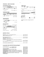
Page 4: ...2 1 TECHNICAL SPECIFICATIONS 98 ...
Page 5: ...2 2 ...
Page 6: ...3 1 CONNECTION AND CONTROLS ...
Page 7: ...3 2 CONNECTION AND CONTROLS ...
Page 8: ...3 3 CONNECTION AND CONTROLS ...
Page 11: ...5 1 5 1 SOFTWARE VERSION CHECKING AND UPGRADING ...
Page 12: ...SET BLOCK DIAGRAM 6 1 6 1 ...
Page 13: ...7 1 7 1 MAIN PCB DVD LOADER TAPE PCB CONTROL PCB TUNER PCB Transformer SET WIRING DIAGRAM ...
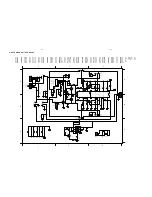
Page 16: ...1 2 3 4 1 2 4 3 A B C A B C 9 1 CIRCUIT DIAGARM TUNER BOARD 9 1 ...
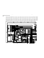
Page 22: ...CIRCUIT DIAGRAM MAIN BOARD PART3 TP120 PADS TEAT 11 3 11 3 ...
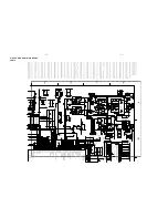
Page 23: ...CIRCUIT DIAGRAM MAIN BOARD PART4 5 11 4 11 4 ...


