background image

PIN DESCRIPTION OF INTEGRATED CIRCUITS

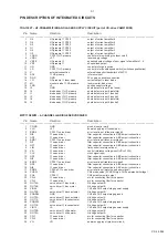
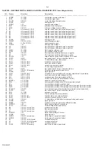
TDA1300T – HF-PREAMPLIFIER AND LASER SUPPLY CIRCUIT (part of CD-drive VAM2103/08)

Pin

Name

Direction

Description

–––––––––––––––––––––––––––––––––––––––––––––––––––––––––––––––––––––––––––––––––––––––––––––––––––––––––––

1

O4

HF-preamp 

CD10

output of current amplifier 4

2

O6

HF-preamp 

CD10

output of current amplifier 6

3

O3

HF-preamp 

CD10

output of current amplifier 3

4

O1

HF-preamp 

CD10

output of current amplifier 1

5

O5

HF-preamp 

CD10

output of current amplifier 5

6

O2

HF-preamp 

CD10

output of current amplifier 2

7

LDON

CD10 

HF-preamp

control pin for switching the laser on/off

8

VDDL

+2.7

laser supply voltage

9

VRFE

HF-preamp 

equalized output voltage of sum signal of amplifiers 1...4

10

VRF

HF-preamp 

unequalized output

11

HG

GND

control pin for gain switch

12

LS

CD10 

HF-preamp

control pin for double speed switch (switches equalization)

13

C

external connection

external capacitor (bandwidth of ALPC)

14

ADJ

HF-preamp

reference input

15

GND

GND

0V supply, substrate connection

16

LO

HF-preamp 

laser diode

current output to laser diode

17

MI

monitor diode 

HF-preamp

laser monitor diode input

18

VDD

+3

positive supply voltage

19

I2

GND

photo detector input 2 (not used)

20

I5

diode array 

HF-preamp

photo detector input 5 (satellite)

21

I1

diode array 

HF-preamp

photo detector input 1 (central)

22

I3

diode array 

HF-preamp

photo detector input 3 (central)

23

I6

diode array 

HF-preamp

photo detector input 6 (satellite)

24

I4

diode array 

HF-preamp

photo detector input 4 (central)

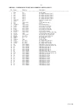
MPC17A50VM – 4-CHANNEL H-BRIDGE SERVODRIVER

Pin

Name

Direction

Description

–––––––––––––––––––––––––––––––––––––––––––––––––––––––––––––––––––––––––––––––––––––––––––––––––––––––––––

1

CGND

GND

ground (control part)

2

VLG

+2.7

power supply input (control part)

3

ERR2

CD10 

servo driver

error level input  (slide error signal)

4

NI2

servo driver

filter capacitor connection in ABS amp circuit section

5

OP2

servo driver

filter capacitor connection in ABS amp circuit section

6

ERR1

CD10 

servo driver

error level input (focus error signal)

7

NI1

servo driver

filter capacitor connection in ABS amp circuit section

8

OP1

servo driver

filter capacitor connection in ABS amp circuit section

9

LIM

servo driver

limit control level signal input

10

VR

servo driver

control reference voltage input (VR=VLG/2)

11

CLK

servo driver

clock signal input

12

OP3

servo driver

filter capacitor connection in ABS amp circuit section

13

NI3

servo driver

filter capacitor connection in ABS amp circuit section

14

ERR3

CD10 

servo driver

error level input (radial error signal)

15

OP4

servo driver

filter capacitor connection in ABS amp circuit section

16

NI4

servo driver

filter capacitor connection in ABS amp circuit section

17

ERR4

CD10/µP 

servo driver

error level input (motor speed error signal)

18

PHSW

GND

CH4 mode setup (if PHSW=high, CH4 operates half-bridge)

19

POL

CD10 

CH4 polarity monitor output

20

CFL4

servo driver

pin for connecting filter for capacitor

21

CFL3

servo driver

pin for connecting filter for capacitor

22

OUT4A

servo driver 

disc motor

H-bridge output A

23

OUT4B

servo driver 

disc motor

H-bridge output B

24

VIN34

+A

CH3 and CH4 output stage power supply

25

OUT3B

servo driver 

track actuator

H-bridge output B

26

PGND34

GND

CH3 and CH4 output stage ground

27

OUT3A

servo driver 

track actuator

H-bridge output A

28

OUT1A

servo driver 

focus actuator

H-bridge output A

29

PGND12

GND

CH1 and CH2 output stage ground

30

OUT1B

servo driver 

focus actuator

H-bridge output B

31

VIN12

+A

CH1 and CH2 output stage power supply

32

OUT2B

servo driver 

slide motor

H-bridge output B

33

OUT2A

servo driver 

slide motor

H-bridge output A

34

CFL1

servo driver

pin for connecting filter for capacitor

35

CFL2

servo driver

pin for connecting filter for capacitor

36

VG

VG

power supply input (predriver circuit)

3-1

CS 46 666

Summary of Contents for AZ 9011

Page 1: ...de view 4 5 Exploded view 5 1 5 3 Mechanical partslist 5 1 Electrical partslist 6 1 6 4 CS 46 658 3103 785 25010 Published by PW 0005 Service Audio Printed in The Netherlands Subject to modification Portable compact disc player CLASS 1 LASER PRODUCT AZ7902 AZ9001 AZ9002 AZ9003 AZ9011 AZ9101 AZ9102 AZ9103 AZ9104 AZ9106 AZ9111 AZ9113 AZ9141 AZ9142 AZ9143 AZ9201 AZ9202 AZ9203 AZ9211 AZ9213 AZ9214 AZ9...

Page 2: ...logy ST1700B i e 4822 395 30204 22kHz 13th order E G A T S B B D e s n o p s e r y c n e u q e r F z H k 3 6 z H k 1 z H k 0 1 1 B B D B d 6 B d 2 B d 0 B d 2 B d 0 B d 2 2 B B D B d 9 B d 2 B d 0 B d 2 B d 5 B d 2 E D O M N O I T A R E P O V 5 4 Y L P P U S N I C D V 5 2 2 Y L P P U S T T A B F F O P S E N O P S E F F O P S E N O P S E e d o m y a l P p y t A m 0 0 1 p y t A m 0 0 1 p y t A m 0 2...

Page 3: ...ter Loose connection Connect the adapter securely In car use Cigarette lighter is not Switch on ignition or insert powered when ignition is off batteries nF d1SC CD RW CD R is not Use FINALIZE on the indication recorded properly CD Recorder to complete the recording no d1SC The CD is badly scratched Replace or clean the CD indication or dirty CD is not or incorrectly inserted Insert a CD label upw...

Page 4: ... AY3170 02 AC DC Adaptor AY3170 05 AC DC Adaptor AY3170 09 AC DC Adaptor AY3170 10 AC DC Adaptor AY3170 12 AC DC Adaptor AY3170 13A AC DC Adaptor AY3170 17 AC DC Adaptor AY3266 00 Pouch Neoprene AY3362 00 Rechargable Batt NiMH AY3501 00 Car Adaptor Cassette AY3545 00 Car DC DC Converter AY3677 00 Earphone L plug AY3677 00S Earphone straight plug AY3682 00 Headphone L plug AY3767 00 Cord Remote Con...

Page 5: ...parts which are identical with those specified be used Safety components are marked by the symbol i Le norme di sicurezza estigono che l apparecchio venga rimesso nelle condizioni originali e che siano utilizzati i pezzi di ricambiago identici a quelli specificati Componenty di sicurezza sono marcati con ñ Veiligheidsbepalingen vereisen dat het apparaat in zijn oorspronkeliijke toestand wordt teru...

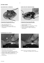
Page 6: ...r 3 Lift the top cabinet and put it backwards on the table 4 Supply the unit via the external DC socket 5 Take care that the door switch is closed during measurements REPAIR POSITION COMPONENTSIDE DISMANTLING THE CD DOOR To dismantle the CD door proceed as follows 1 Disconnect the membrane keyboard flex foil connector on copperside of printed board 2 Smoothly bend the bridge of the cabinet downwar...

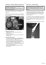
Page 7: ...o the inner and outer position to spread the grease 3 Put one dot of grease between the worm gear and the clamping spring VAM2103 08 LENS CLEANING Because the material of the lens is synthetic and coated with a special anti reflectivity layer cleaning must be done with a non aggressive cleaning fluid It is advised to use KODAK LENS CLEANER CAT 176 71 36 available in normal photo shops The actuator...

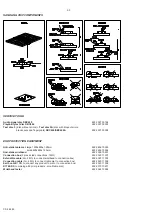
Page 8: ...650x1 25mm 4822 466 10953 small 600x650x1 25mm 4822 466 10958 Anti static wristband 4822 395 10223 Connection box 3 press stud connections 1MΩ 4822 320 11307 Extendible cable 2m 2MΩ to connect wristband to connection box 4822 320 11305 Connecting cable 3m 2MΩ to connect table mat to connection box 4822 320 11306 Earth cable 1MΩ to connect any product to mat or to connection box 4822 320 11308 KIT ...

Page 9: ...ervo driver filter capacitor connection in ABS amp circuit section 6 ERR1 CD10 servo driver error level input focus error signal 7 NI1 servo driver filter capacitor connection in ABS amp circuit section 8 OP1 servo driver filter capacitor connection in ABS amp circuit section 9 LIM servo driver limit control level signal input 10 VR servo driver control reference voltage input VR VLG 2 11 CLK serv...

Page 10: ...in should be tied low 32 KILL CD10 HF preamp kill output programmable open drain 33 VSSD1 GND digital ground 2 34 V2 V3 CD10 NPC versatile I O input versatile pin 2 or output versatile pin 3 open drain 35 WCLI NPC CD10 word clock input for data loopback to DAC 36 SDI NPC CD10 serial data input for data loopback to DAC 37 SCLI NPC CD10 serial bit clock input for data loopback to DAC 38 RESETn µP CD...

Page 11: ...ubcode block clock signal output 20 RESET µP NPC system reset input active low 21 ZSENSE NPC µP µP interface status output 22 VDD2 3 supply voltage 23 YDMUTE GND forced mute input 24 YMLD µP NPC µP interface latch clock input 25 YMDATA µP NPC µP interface serial data input 26 YMCLK µP NPC µP interface shift clock input 27 OE NPC DRAM DRAM OE control output active low 28 CAS NPC DRAM DRAM CAS contr...

Page 12: ...tor circuit 12 ALC DET headphone amp smoothing for ALC detection GND ALC off open ALC ON 13 ATT headphone amp power amplifier gain switch open VCC ATT off GND ATT on 14 IN A headphone amp input of power amplifier 15 IN B headphone amp input of power amplifier 16 GND GND ground of input stage in power amplifier 17 BEEP IN µP headphone amp input terminal for beep sound 18 MUTE TC headphone amp termi...

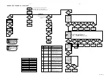
Page 13: ...or ext DC supply no accu inserted hold switch in off pos ESA on resume mode off CD door closed N N N Y TOC found within 30s N Y Y Y POWER OFF stand by focus found within 1s µP accelerates disc to nom speed DC DC converter is switched on radial jump check error release MUTE µP initializes radial servo loop N Y Y Y subcode check error Y N N N PLAY MODE subcode check error handler radial check error ...

Page 14: ...o test and return to the main menu press the STOP button 6 FOCUS TEST Purpose Check movement of lens and operation of focus servo in normal and CD RW compatible mode The focus servo loop is switched on and the set starts searching the focus focus ramping As soon as the focus has been found the focus servo loop is closed and the state of the focus is monitored continuously If the focus is OK the di...

Page 15: ... fatal fatal CAUSE Focus point lost for at least 3ms The radial servo was offtrack for a certain amount of time The slide did not reach it s inner pos inner switch of CD drive doesn t close within approx 6 seconds The slide did not come out of it s inner pos inner switch of CD drive is open within approx 250ms The DRAM controller was not able to connect two consecutive audio frames The microcontro...

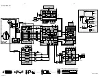
Page 16: ...ECTOR 2xVOLTAGE DOUBLER DM_IN VLG VR CLK DM_PWM FROM µP CLsaw VG VLG VR CLsaw 2 7 VG A Track L P F L P F L P F FLEX PCB DC in socket ACCU or BATTERY charge ACCU DETECT SUPPLY CHARGE CIRCUIT BEEP CHG_ON TEMP DC_IN MUTE HP_ON ACCU_IN CHG_DET BAT_LEVEL DM_PWM TO SERVO PORES TO CD10 NPC_RESET TO NPC DBB_ON DBB_STEP DC DC UP DOWN CONVERTER NPC_RESET FROM µP RESET PORES FROM µP RESET ACCU_IN TO µP TEMP ...

Page 17: ...R 2891 560p 7890 BC857BW 3891 1K2 BC857BW 7891 2809 1n 3808 1K 7800 BC857BW 3810 470K 3811 2K2 3812 22K 2813 2n2 2814 22p 2816 10n 3879 2815 22n D 0R D 3878 0R 2872 100n D 0R 3880 22R 0R 3871 3872 0R 3873 0R 3875 3877 0R 3874 0R 3876 0R 5 4 3 26 25 24 23 22 21 7870 DRAM_16 4 BIT 16 15 14 13 12 11 10 1 9 8 6 2800 1n5 2801 560p 2 19 18 17 220p 2807 2806 220p 2803 220p 2805 220p 220p 2804 WCLK 28 WCL...

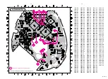
Page 18: ...TO 7801 PART1 FROM 1400 FROM 1350 PART1 TO 7260 PART3 1 2 3 4 3402 C6 3403 C6 3404 D1 3405 D1 3406 A5 3407 F3 3408 F6 3409 F6 3411 E6 3412 D1 3415 A6 3416 A6 3417 A5 5400 F2 7400 B2 2400 C2 2401 D2 3400 A6 3401 A6 DOORSWITCH R only for Cord R C R 1K 3416 220K 3409 5K6 3405 3415 1K 1n 2405 2M2 3408 18 5 1 2 3 220K 3406 42 43 8 51 50 49 48 47 46 45 44 4 58 57 56 34 35 10 11 12 13 14 15 16 17 36 37 3...

Page 19: ... 6 3261 10K 220n 2271 2276 47p 8K2 3262 2 7V A 2 7V 1 25V 7951 7951 A A S_MUTE 3V UP UP 2 7V BATT_LEVEL 1 25V DM_PWM DC_IN DC 1 25V 2 7V TEMP RESET POWER UP ACCU_IN A DC DC CHG_ON CLK 2 7V CHG_DET UP PART3 SUPPLY 1250 B1 1251 A3 2243 E8 2251 B7 2252 A7 2253 A8 2254 C7 2255 B8 2256 C9 2257 B9 2258 A9 2259 A10 2260 B10 2261 B10 2262 B10 2263 D9 2264 D10 2266 D10 2267 D1 2268 E2 2269 B5 2271 E9 2272 ...

Page 20: ... G5 3257 B7 3282 G6 3294 E7 3295 E8 3300 H2 3301 F2 3302 F3 3303 F2 3304 G2 3305 F2 3308 G3 3309 F2 3310 G2 3311 F2 3312 G2 3313 G2 3314 G3 3315 F3 3317 G2 3318 F2 3320 G1 3321 G1 3322 G1 3323 G1 3349 F2 3350 D1 3351 G3 3363 G2 3364 G3 3366 G2 3367 F1 3800 D1 3801 E2 3808 D1 3809 F2 3822 D1 3835 D1 3870 C1 3871 C1 3877 C1 3878 B2 3879 B2 3881 D1 3951 I3 3952 H4 3953 I3 3954 H4 3955 H4 3957 H3 5250...

Page 21: ...2 3292 F2 3293 F2 3296 E2 3297 E2 3298 E2 3299 E3 3316 H6 3352 F7 3353 G7 3354 G7 3355 G7 3356 H7 3357 G7 3359 G6 3360 G6 3361 F7 3362 G6 3365 H6 3400 C4 3401 B4 3402 C4 3403 C4 3404 B2 3405 C2 3406 B4 3407 D2 3408 D3 3409 C2 3411 D4 3412 B3 3415 C4 3416 C4 3417 C4 3802 E6 3803 E6 3804 E6 3805 E7 3807 D7 3810 F6 3811 F6 3812 E5 3813 E5 3814 G5 3815 D3 3816 E3 3817 D4 3818 D4 3819 E3 3820 D3 3821 D...

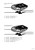
Page 22: ...version 411 3103 301 06520 SPRING OPEN LONG L 2C45 412 3103 301 06510 SPRING OPEN LONG R 2C45 413 3103 304 68090 BRAKE 2 414 3103 301 45180 SPRING BATTERY SHORT 2 416 9305 022 13208 CD DRIVE VAM2103 08 417 4822 402 10897 DAMPER CD DRIVE 418 3103 301 45200 SPRING BATTERY MINUS 2 419 3103 301 45190 SPRING BATTERY PLUS 2 421 3103 301 45210 SPRING BATTERY CHARGE 2 422 4822 462 41819 RUBBER FOOT 4822 5...

Page 23: ... follows DOOR CD ASSEMBLY 2C40B TRANSLUCENT RED 40s ESP 451 3103 307 99240 DOOR CD ASSEMBLY 2C45 SILVER 45s ESP 451 3140 117 59760 DOOR CD ASSEMBLY 2C45G TRANSLUCENT GREEN 45s ESP 452 3103 307 98320 BUTTON SET PLAY 2C40SQ LAC PRI 453 3103 307 97970 BUTTON PREV 1C LAC 454 3103 307 97980 BUTTON NEXT 1C LAC 451 3103 307 99200 DOOR CD ASSEMBLY 1C SILVER 452 3103 307 97960 BUTTON SET PLAY 1C LAC 453 31...

Page 24: ...ows DOOR CD ASSEMBLY 2J40G GREEN 40s ESP 451 12NC follows DOOR CD ASSEMBLY 2J40P PURPLE 40s ESP 451 12NC follows DOOR CD ASSEMBLY 2J45 SILVER 45s ESP 452 3103 307 98040 BUTTON SET ALL 2J45 LAC PRI 451 3103 307 99210 DOOR CD ASSEMBLY 2C12 SILVER 12s ESP 451 3140 117 59750 DOOR CD ASSEMBLY 2C12B TRANSLUCENT BLUE 12s ESP 452 3103 307 98210 BUTTON SET PLAY 2C12 LAC PRI 453 3103 307 98010 BUTTON PREV 2...

Page 25: ...10 16V 2364 5322 126 11583 10nF 10 63V 2365 4822 124 40998 22µF 20 6 3V CAPACITORS 2366 4822 124 11947 10µF 20 16V 2367 2238 780 15654 220nF 10 16V 2368 4822 124 22652 2 2µF 20 50V 2369 4822 126 14305 100nF 10 16V 2370 4822 126 14305 100nF 10 16V 2400 4822 126 14305 100nF 10 16V 2401 4822 126 14305 100nF 10 16V 2402 4822 126 14305 100nF 10 16V 2403 4822 126 14083 4 7µF 20 10V 2404 4822 126 14043 1...

Page 26: ...12925 47kΩ 1 0 0625W 3295 4822 117 12891 220kΩ 1 0 0625W 3296 4822 117 13632 100kΩ 1 0 0625W 3297 4822 117 13632 100kΩ 1 0 0625W 3298 4822 051 30183 18kΩ 5 0 06W 3299 4822 051 30103 10kΩ 5 0 06W 3300 3103 308 52850 POTMETER ALPS 2x10kΩ CX2 3301 4822 051 30223 22kΩ 5 0 06W 3302 4822 051 30223 22kΩ 5 0 06W 3303 4822 051 30223 22kΩ 5 0 06W 3304 4822 051 30332 3 3kΩ 5 0 0625W 3305 4822 051 30332 3 3kΩ...

Page 27: ...JUMPER 0603 3880 4822 117 12139 22Ω 5 0 0625W 3881 4822 051 30103 10kΩ 5 0 06W 3882 4822 051 30103 10kΩ 5 0 06W 3890 4822 051 30222 2 2kΩ 5 0 06W 3891 4822 117 11817 1 2kΩ 1 0 0625W 3892 4822 051 30221 220Ω 5 0 06W 3893 4822 051 30223 22kΩ 5 0 06W 3894 4822 051 30223 22kΩ 5 0 06W 3895 4822 051 30103 10kΩ 5 0 06W 3951 3198 021 90030 CHIP JUMPER 0603 RESISTORS 3952 4822 051 30682 6 8kΩ 5 0 0625W 395...

Page 28: ...ONE AMPLIFIER 7400 3103 308 84100 TMP86CH29LF AZ9000 2 7801 9352 641 80557 SAA7324H M2B CD10 M2B 7850 9322 142 87671 SM5903BF NPC 7870 4822 209 16518 HYB314400BJ 60 4Mbit DRAM 7870 9322 138 26668 MSM51V17405D 60TS K 16Mbit DRAM 7950 4822 209 16085 MPC17A50VM SERVO DRIVER 7951 9322 142 72685 TC75W51FU 7958 9322 142 72685 TC75W51FU 6 4 CS 46 685 ...

Reviews: