Mechanical Instructions
4.
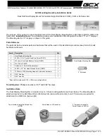
4.10.2 Small Signal Board (SSB)
Refer to
for details.
Caution: it is mandatory to remount all different screws at their
original position during re-assembly. Failure to do so may result
in damaging the SSB.
1.
Release the clips from the LVDS connector that connect
with the SSB [1].
Caution: be careful, as these are very fragile connectors!
2.
Unplug all other connectors [2].
3.
Remove all the fixation screws from the SSB [3].
4.
The SSB can now be shifted from side connector cover,
then lifted and taken out of the I/O bracket. Refer to
for details.
Figure 4-39 SSB removal
4.10.3 Power Supply Unit (PSU)
Caution: it is mandatory to remount all different screws at their
original position during re-assembly. Failure to do so may result
in damaging the PSU.
1.
Gently unplug all connectors from the PSU.
2.
Remove all fixation screws from the PSU.
3.
The PSU can be taken out of the set now.
4.10.4 Speakers
1.
Unplug the speaker connectors from the SSB.
2.
Remove all the fixation screws that secure the speakers.
3.
Gently release the tapes that secures the speaker cables.
4.
Take the speakers out.
When defective, replace the both units.
4.10.5 Stand bracket
1.
Remove all fixation screws of the bracket.
2.
Lift the bracket from the set.
4.10.6 Keyboard Control unit
1.
Unplug the connector from the SSB.
2.
Remove the fixation screw that secure the keyboard
control panel.
3.
Unplug the connector from the keyboard control panel.
4.
Gently release the tapes taht secures the keyboard cables.
5.
Take the keyboard out.
When defective, replace the whole unit.
4.10.7 IR/LED Panel
1.
Remove the stand bracket, as described earlier.
2.
Remove fixation screw that secure the deco rear cover and
take it out from the deco.
3.
Unplug the connector from the IR/LED panel.
4.
Gently release the double faced adhesive tape that pasted
the panel and take it out from the deco.
When defective, replace the whole unit.
4.10.8 WIFI module
1.
Unplug the connector from the SSB.
2.
Remove fixation screw that secure the WIFI module,
getntly remove the module from the set.
When defective, replace the whole unit.
4.10.9 LCD Panel
1.
Unplug all the connector cables of the boards.
2.
Lift the subframe with SSB, PSU, IR/LED board and WIFI
module panel from the LCD panel and put it aside.
3.
Gently take all the speakers out.
Warning:Cause the panels of 55" 5600 series are bolt-on
panels, the panel could not release from bezel.
When defective, replace the whole unit.
4.11 Assembly/Panel Removal (for 55" 6500 series)
Instructions below apply to the 55PFT6569/60, but will be
similar for other 55" 6500 series models.
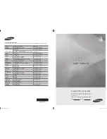
4.11.1 Rear Cover
Refer to
for details.
Warning: Disconnect the mains power cord before removing
the rear cover.
1.
Remove fixation screws [1] that secure the base assy, pull
out the base assy from the set. Then remove the fixation
screws [2,3,4] that secure the rear cover. Refer to
2.
Gently lift the rear cover from the TV. Make sure that wires
and cables are not damaged while lifting the rear cover
from the set.
19605_109.eps
2
1
3
3
3
3