


7-1
PL10.4FW
FIRMWARE RENEWAL MODE
Equipment Required
a. USB storage device
b. Remote Control Unit
Firmware Update Procedure
1. Turn the power off and unplug the AC Cord.
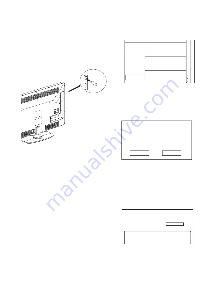
2. Insert the USB storage device to the USB port as
shown below.
3. Plug the AC Cord and turn the power on.
4. After few seconds, the menu mode will appear on
the screen.
Note:
After 30 seconds without an operation, the menu
mode will disappear automatically.
To display the menu mode again, press the
[MENU] button on the remote control unit.
5. Select “Setup” and press the [OK] button to display
the setup menu.
6. Select “Software update”.
7. Select “Updates”.
8. Select “USB”.
9. Press the [OK] button on the remote control unit to
enter the update mode.
Update file selection screen appears as follows.
(Files included in the USB storage device are
displayed.)
Note:
To cancel the update mode, select “Cancel” and
press the [OK] button.
10. Select the file and press [OK] button.
11. The update will start and the following will appear
on the screen.
Note:
If the above screen isn’t displayed, repeat from
step 1.
12. Select “Yes” and press the [OK] button to update.
Note:
Do not remove the USB storage device or turn the
TV off while update is in progress.
13. When the firmware update is completed, the
following will appear on the screen.
Remove the USB storage device from the USB
port.
Turn the power off and turn the power on again.
USB port
USB storage
device
Rear Cabinet
Select an upgrade file
Cancel
*****_******.upg
*****_******.upg
*****_******.upg
"*" differs depending on the models.
1 2 3
Are you sure you want to update?
No
Yes
Current Version:
New Version:
***-***-***-***-* ********-******
*******-***-*-***-****
"*" differs depending on the models.
Update your TV with new software:
Done
Software update is successful.
Please remove the USB storage device
and restart the TV set.
Summary of Contents for 40PFL5505D/F7
Page 14: ...4 2 PL10 4DC 2 Rear Cabinet S 1 1 Stand Assembly S 2 S 2 S 2 S 2 S 2 S 2 S 2 S 3 Fig D1 ...
Page 42: ...10 14 PL10 4SCD12 Digital Main 12 Schematic Diagram ...
Page 43: ...10 15 PL10 4SCD13 Digital Main 13 Schematic Diagram ...
Page 45: ...10 17 PL10 4SCF Function Schematic Diagram ...
Page 46: ...10 18 PL10 4SCIR IR Sensor Schematic Diagram ...


