!"
Changing
the
TV
system
If
you
play
recordings
made
on
another
video
recorder
or
if
you
record
from
another
source,
the
automatic
TV
system
switch-over
may
lead
to
colour
distortion.
You
can
switch
off
the
automatic
TV
system
switch-over
as
follows:
a
Press
MENU
on
the
remote
control
before
you
start
recording
or
during
playback
.The
main
menu
will
appear.
b
Select
the
line
’
SPECIAL
SETTINGS
’with
the
buttons
=
P
r
or
;
P
q
and
confirm
with
the
SqP
button.
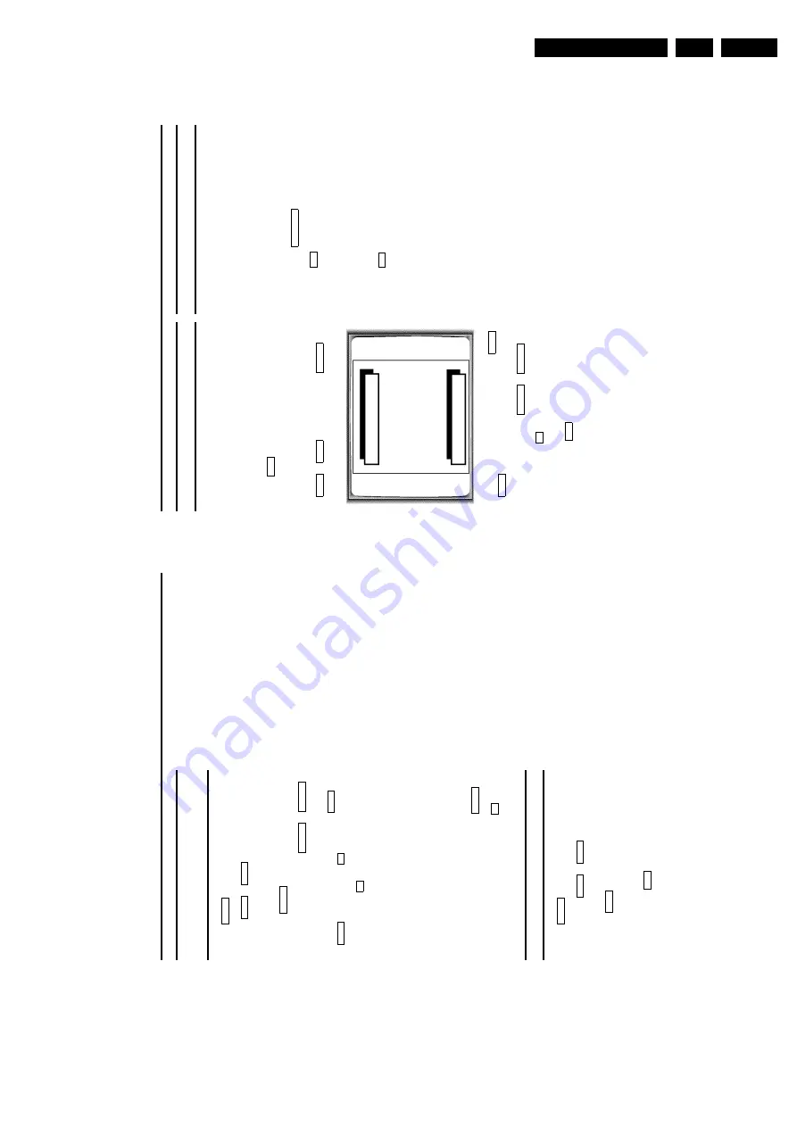
SPECIAL
SETTINGS
RECORD
SPEED
W
SP
X
TV
SYSTEM
PAL
OSD
AUTO
SAT
RECORDING
OFF
EXIT:
MENU
STORE:
OK
c
Select
the
line
’
TV
SYSTEM
’with
the
buttons
;
P
q
or
=
P
r
.
d
Select
the
TV
system
with
SqP
or
QSr
.
e
Confirm
with
the
OK
button.
’
STORED
’will
briefly
appear
on
the
screen.
f
To
end,
press
the
MENU
button.
D
If
you
change
the
programme
number,
the
TV
system
is
switched
back
to
automatic
switch-over
for
the
recording.
D
If
you
eject
the
cassette,
the
TV-system
for
playback
will
switch
to
’
AUTO
’(automatic
switch-over)
again.
Parental
control
(Child
lock)
This
function
protects
your
TV-Video
Combi
from
unwanted
use.
All
button
functions
on
the
front
of
the
machine
are
blocked.
D
Programmed
recordings
will
still
be
recorded
(in
spite
of
the
parental
control)
and
cannot
be
interrupted.
a
Please
make
sure
the
TELETEXT
decoder
is
switched
off
using
the
button
TELETEXT
e
.
b
Press
the
u
button
on
the
remote
control
for
approx.
5
seconds
.
The
standby
lamp
(
STANDBY
5
)
o
n
the
front
of
the
machine
blinks
for
approx.
3
seconds
to
confirm
this
action.
Keep
the
remote
control
in
a
safe
place.
c
If
you
want
to
switch
the
parental
control
function
off,
press
the
u
button
on
the
remote
control
for
approx.
5
seconds
.
The
standby
lamp
(
STANDBY
5
)
o
n
the
front
of
the
machine
blinks
for
approx.
3
seconds
to
confirm
this
action.
D
If
a
button
at
the
front
of
the
machine
is
pressed
while
parental
control
is
active,
’
CHILD
LOCK
ACTIVE
’will
appear
on
the
screen
for
a
few
seconds.
The
standby
lamp
(
STANDBY
5
)
blinks
as
long
as
a
button
on
the
front
is
pressed.
8.
ADDITIONAL
FUNCTIONS
How
to
check
or
change
a
programmed
recording
(TIMER)
a
Press
TIMER
k
on
the
remote
control
twice
.
b
Use
the
=
P
r
or
;
P
q
buttons
to
select
the
programmed
recording
(TIMER)
you
wish
to
check
or
change.
c
Press
the
TIMER
k
button.
d
Select
the
entry
field
with
the
QSr
or
SqP
button.
e
Change
any
displayed
information
with
the
=
P
r
or
;
P
q
button
or
with
the
0..9
buttons.
f
Confirm
with
the
OK
button.
g
Make
sure
that
the
cassette
you
have
inserted
is
not
erase
protected.
D
TIMER
recording
only
functions
if
the
machine
is
not
being
used
for
other
video
recorder
functions
like
for
example
for
playback.
D
If
the
TV-Video
Combi
is
used
a
few
minutes
before
beginning
a
programmed
recording
session
for
playback
(for
example),
’
PRESS
OK
TO
START
RECORDING
’will
appear
on
the
screen.
Change
cassettes
or
press
the
button
STOP
h
if
you
want
to
use
this
cassette
for
recording.
Confirm
this
message
with
the
button
OK
,t
o
continue
the
programmed
recording
session.
Clearing
a
programmed
recording
(TIMER)
a
Press
TIMER
k
on
the
remote
control
twice
.
b
Use
the
button
=
P
r
or
;
P
q
to
select
the
programmed
recording
(TIMER)
which
you
wish
to
clear.
c
Press
the
CLEAR
button.
The
selected
programmed
recording
(TIMER)
has
now
been
deleted.
d
To
end,
press
the
MENU
button.
Summary of Contents for 14PV110/01
Page 24: ... 2 3 3 5 6D 2 2 5 6D 1 2 43 5 6D 7 5 6D 3 0 5 6 2 D 4 D N 6 6 7 8 9 0 N 2 G C D N 2 D ...
Page 25: ... 2 3 5 6D D 0 2 D 5 6 2 5 6D 2 D 5 2 P 5 D 6D D 2 2 5 6D D D 0 2 D 2 D ...
Page 34: ...34 14PV110 6 Block Diagrams Waveforms Wiring Diagram 6 2 Block Diagram Audio ...
Page 35: ...Block Diagrams Waveforms Wiring Diagram 35 14PV110 6 6 3 Block Diagram Deck Control ...
Page 36: ...36 14PV110 6 Block Diagrams Waveforms Wiring Diagram 6 4 Block Diagram Supply Deflection ...
Page 40: ...40 14PV110 6 Block Diagrams Waveforms Wiring Diagram 6 7 Wiring Diagram 14 ...
Page 41: ...Block Diagrams Waveforms Wiring Diagram 41 14PV110 6 6 8 Wiring Diagram 20 21 ...
Page 62: ...62 14PV110 7 Circuit Diagrams and PWB Layouts 7 22 Small Signal Board SSB Components Side ...
Page 63: ...Circuit Diagrams and PWB Layouts 63 14PV110 7 7 23 Small Signal Board SSB Solder Side ...
Page 65: ...Circuit Diagrams and PWB Layouts 65 14PV110 7 7 25 Large Signal Board LSB1L 14 Solder Side ...
Page 68: ...68 14PV110 7 Circuit Diagrams and PWB Layouts 7 29 Large Signal Board LSB2L 20 21 Solder Side ...
Page 89: ... ...
Page 99: ... ...
Page 103: ... 1 ...
Page 104: ... 1 6 2 ...
Page 109: ... µ µ µ µ µ µ µ µ µ µ µ µ µ µ µ µ µ Ω Ω Ω µ µ µ µ µ µ µ µ µ µ µ 8 ...
Page 114: ... A 9 7 A A 9 7 A 1 45 012 3 3 1 45 012 3 1 45 012 3 1 45 012 3 3 ...


