background image

06-10-2020 14

:

42

Pagina 3 van 9

http://manual.zwave.eu/backend/make.php?lang=en&sku=PHI_PST02-1B

Choosing a Suitable Location

The recommended mounting height is 160cm

Don"t let the device facing the window or the sunlight.

Don"t let the device facing the source of heat. For instance the heater or the air-condition.

Installation

In the first time, add the device into the Z-WaveTM network. First, make sure the primary controller is in the inclusion mode. And then power on the devi
take out the insulation Mylar in the back side of the device. The device will auto start the NWI (Network Wide Inclusion) mode. And it should be included
seconds. You will see the LED light ON one second. 

Let the controller associate with the device into the first group, any light switch that intend to be turned on when the device trig please associate with the
into the second group. 

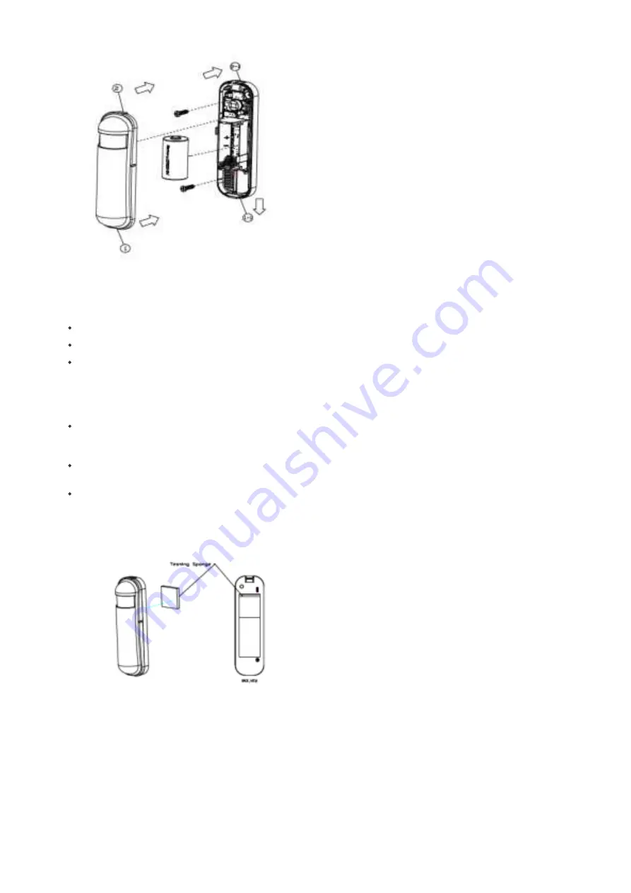
In the accessory pack. There are two type of double coated tape, one is thicker (hereinafter referred to as A tape) and another is thinner (hereinafter refe
as B tape), you can use A tape for the test at the beginning. The right way for A tape installation is stick it to the position below tamper key. The thicker ta
won"t let the tamper key pressed, so the sensor will enter the test mode, You may test if installed position is good or not by this way.

After finish the test and decide to fix, then you can remove tape A, and mounting the sensor by using tape B. The tamper key will pressed and let the senso
normal mode. 

Summary of Contents for PHI PST02-1B

Page 1: ...t as a repeater for other nodes meshed network in case the receiver is not in direct wireless range of the transmitter This device and every other certified Z Wave device can be used together with any other certified Z Wave device regardless of brand and origin as long as both are suited for the same frequency range If a device supports secure communication it will communicate with other devices sec...

Page 2: ...set without any involvement of a Z Wave controller This procedure should only be used when the primary controller is inope 1 Pressing tamper key four times within 1 5 seconds and do not release the tamper key in the 4th pressed and the LED will light ON 2 After 3 seconds the LED will turn OFF after that within 2 seconds release the tamper key If successful the LED will light ON one second Otherwis...

Page 3: ...nds You will see the LED light ON one second Let the controller associate with the device into the first group any light switch that intend to be turned on when the device trig please associate with the into the second group In the accessory pack There are two type of double coated tape one is thicker hereinafter referred to as A tape and another is thinner hereinafter refe as B tape you can use A ...

Page 4: ...ep state Without such a controller communication may become impossible and or the battery life time significantly decreased This device will wakeup regularly and announce the wakeup state by sending out a so called Wakeup Notification The controller can then empty the mailbo Therefore the device needs to be configured with the desired wakeup interval and the node ID of the controller If the device wa...

Page 5: ...us 256 For example To set a parameter to 200 it may be needed to set a value of 200 minus 256 minus 56 In case of a two byte value the same applies Values greater than 32768 may needed to be given as negative values too Parameter 2 Basic Set Level Setting the BASIC command value to turn on the light Size 1 Byte Default Value 255 Setting Description 0 turn off the light 1 100 the light strength 254...

Page 6: ...tomer function switch using bit control Size 1 Byte Default Value 4 Setting Description 1 Reserve 2 Enable sending motion OFF report 0 Disable 1 Enable 4 Enable PIR super sensitivity mode 0 Disable 1 Enable 8 Reserve 16 Notification Type 0 Using Notification Report 1 Using Sensor Binary Report 32 Disable Multi CC in auto report 1 Disable 0 Enable 64 Disable to report battery state when the device tr...

Page 7: ...27 Auto Report Temperature Time Parameter 20 Auto Report Tick Interval The interval time for auto report each tick Setting this configuration will effect configuration No 10 No 11 No 12 and No 13 Caution Setting to 0 means turn report function Size 1 Byte Default Value 30 Setting Description 0 255 Auto Report Tick Interval Parameter 21 Temperature Differential Report The temperature differential to ...

Page 8: ...mware Update Md Manufacturer Specific Multi Command Sensor Multilevel Notification Powerlevel Security Version Wake Up Zwaveplus Info Controlled Command Classes Basic Explanation of Z Wave specific terms Controller is a Z Wave device with capabilities to manage the network Controllers are typically Gateways Remote Controls or battery operated wall controllers Slave is a Z Wave device without capabili...

Page 9: ...vice to announces that is able to communicate Node Information Frame is a special wireless message issued by a Z Wave device to announce its capabilities and functions c 2020 Z Wave Europe GmbH Antonstr 3 09337 Hohenstein Ernstthal Germany All rights reserved www zwave eu The template is maintained by Z Wave Europe GmbH The product content is maintained by Z Wave Europe GmbH Supportteam support zw...

Reviews: