background image

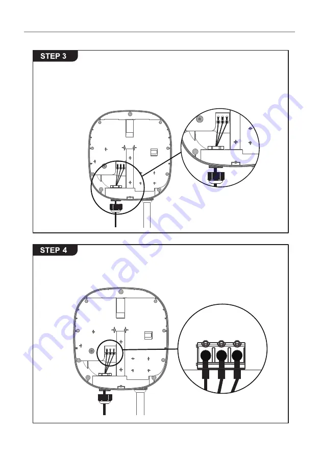
15~18mm of the insulation sheath should be stripped off the 
three AC wires. Take out the included needle terminal and 
install the needle terminal on the three GND/PE, L1/L, L2/N 
wires. Pass the three wires through the M25 waterproof gland 
Part 3.

Insert the three wires into the wire holes of the green terminal 
block to the corresponding GND/PE, L1/L, L2/N and lock them. 
The recommended screw torque is 1.5 N.m (13.3 lbf.in).

AW Series - User Manual

15

Summary of Contents for AW Series

Page 1: ......

Page 2: ...ition Electric Vehicle AC Charger AW Series User Manual COPYRIGHT 2020 Phihong Technology reserves the right to make changes to this product without further notice IP55 Authorization Management Repairable Outdoors version W84A99900088 HB7 ...

Page 3: ...Please visit the official website to obtain the latest version of user manual before installation Website www phihong com tw ...

Page 4: ...ion Requirements 13 7 5 Installation Steps 14 7 6 Wall Mount Bracket Installation 17 8 Operating Instructions 19 8 1 Operating Procedures 19 8 2 Operating Steps Non Networking Edition 19 8 3 Operating Steps Networking Edition 20 8 4 Time setting Networking Wi Fi and 4G Editions 21 8 5 Wi Fi Setup for the optional Wi Fi Edition 23 8 6 4G Setup for the optional 4G Edition 24 8 7 Re checking the Wi F...

Page 5: ...rs Turn off the input power of the charger before performing any maintenance to the charger The device is designed only for vehicles that are compatible with the IEC62196 2 charging standard Do not use the charger if it is defective appears cracked frayed broken or damaged Do not attempt to open disassemble repair tamper with or modify the charger Contact our Customer Service department if you hav...

Page 6: ...ger and the dangers involved Failure to observe this precaution could result in damage to the charger or even severe injury or death Incorrect installation and testing of the charger could potentially damage either the vehicle s battery and the charger This type is damage is not covered by our warranty policy Ensure that the charging cable is well positioned during the charging process to avoid th...

Page 7: ...IEC62196 2 AC Charging Connector Rear Notch Charging Cable Inlet USB Cable Inlet AC Power Inlet LED Light Indication 2 Interface 2 1 Non Networking Edition AW Series User Manual 3 ...

Page 8: ...RJ45 Cable Inlet LED Light Indication IEC62196 2 AC Charging Connector Rear Notch Charging Cable Inlet AC Power Inlet 2 2 Networking Edition RFID Green Power Green Lifestyle 4 ...

Page 9: ...260 280 100 100 80 174 Ø7x4 3 Dimensions unit mm 3 1 Main Size of Charger 3 2 Wall Mount Bracket AW Series User Manual 5 ...

Page 10: ...imum Relative Storage Humidity 95 RH Maximum RFID Authorization Networking Version or Wi Fi Version or 4G Version RJ45 Cable Inlet 1 10M 100M Base T Support software update function Wi Fi Function 2 802 11 b g n 2G 3G 4G Finction 3 LTE UMTS HSPA GSM GPRS EDGE Cable Length 5M From charger s body to lower edge of charging connector Protection Level IP55 Installation Type Wall Mount Altitude 2000 m W...

Page 11: ...charging system Part 1 General requirements IEC 61851 21 2 2018 Electric vehicle conductive charging system Part 21 2 Electric vehicle requirements for conductive connection to an AC DC supply EMC requirements for off board electric vehicle charging systems AW Series User Manual 7 ...

Page 12: ... lit during standby mode RFID Authorization Internet Edition Green Light Flashing The Green light is flashing after the RFID is authorized Waiting for Charging Blue Light After the vehicle connector is connected to the vehicle inlet the CHARGE light is constantly lit Green Power Green Lifestyle 8 ...

Page 13: ...Red Light The red light is lit during fault Please refer to 8 4 Error and Warning Messages for detailed information Charging Blue Light Flashing The CHARGE light flashes while charging AW Series User Manual 9 ...

Page 14: ...on must be bonded in the upstream power supply for proper operation Check all physical connections including the wirebox terminals electrical panel s and junction boxes In residential power supplies check the bond between Ground and neutral at the main panel If connected to a step down transformer contact the transformer s manufacturer for direction on how to bond the ground connection Power Grid ...

Page 15: ...ct our technical staff for assistance and confirmation Note 4 Regarding BS7671 2018 section 722 EVSE cannot use in the TN C S grounding system in UK Note 5 The default value for Japan is 30A Note 6 The default value in other countries is 32A 120V 120V 208V PE L1 L2 V 2 V 2 V PE L1 L2 0 V V PE L N V 240 or 200 volt Charger input terminal Charger input terminal Charger input terminal V 240 or 230 or...

Page 16: ... 7 8 R F I D 9 RFID Version 10 1 Notice According to EN 17186 requirement this document lays down harmonized identifiers for power supply for electric road vehicles The requirements in this standard are to complement the informational needs of users regarding the compatibility between the EV charging stations the cable assemblies and the vehicles that are placed on the market The identifier is int...

Page 17: ...nstall the bracket and use a cement drill to drill holes on the cement wall Ø8mm following the hole spacing in accordance with 3 2 When installing on a wooden wall you can directly use the included M6 self tapping screws to install the wall mount bracket and use the back Mount backplane to lock and install on the wall directly 7 3 Wall Mount Bracket Installation Requirements To select the best loc...

Page 18: ... Installation Steps Warning for Wi Fi and 4G versions Due to different congenital environments it is recommended to first conduct Wi Fi and 4G module network signal tests before finalizing your settings It is recommended that the RSSI Received Signal Strength Indication value should be higher than 65dBm If it is lower than this value it may result in a weak Wi Fi or 4G connection or disconnection ...

Page 19: ...tall the needle terminal on the three GND PE L1 L L2 N wires Pass the three wires through the M25 waterproof gland Part 3 Insert the three wires into the wire holes of the green terminal block to the corresponding GND PE L1 L L2 N and lock them The recommended screw torque is 1 5 N m 13 3 lbf in AW Series User Manual 15 ...

Page 20: ...6 2 lbf in 5 3 6 For Internet Edition model with 4G function The SIM card slot is located on the right side Insert the SIM card according to the image below Important Note Before installing the SIM card to the charger it is necessary to confirm that the SIM card has been activated and the password has been cancelled Green Power Green Lifestyle 16 ...

Page 21: ...to the wall Mount bracket and align the screw holes of the right and left sides 7 6 Wall Mount Bracket Installation Use the 4 sets of expansion and M6 screws to attach the wall Mount bracket on the wall 1 2 3 4 AW Series User Manual 17 ...

Page 22: ...Attach with the M4 screws to complete the installation 1 2 Overall outlook picture after installation Wall Mount cable winding With Optional Cable Hook optional accessory Green Power Green Lifestyle 18 ...

Page 23: ... will then enter standby mode and the green light READY will remain lit This could take up to 90 seconds STEP1 Standby Mode Plug the charging cable into the vehicle charging inlet The blue light CHARGE is constantly lit STEP2 Connection to Vehicle Inlet When the blue light CHARGE starts to flash automatically the charging process has begun STEP3 Charging When the charging session is complete the b...

Page 24: ...ashes during the charging session If the red light FAULT is lit proceed to plug the vehicle connector again If the red light is still lit please refer to Error and Warning Messages STEP4 Charging After power on the green READY blue CHARGE and red lights FAULT will all light up The charger will then enter standby mode and the green light READY will remain lit This could take up to 90 seconds STEP1 ...

Page 25: ...wer on the green READY blue CHARGE and red lights FAULT will all light up The charger will then enter standby mode and the green light READY will remain lit This could take up to 90 seconds STEP4 Change the IP Address on your laptop computer by accessing the network card settings Change the TCP IP automatic IP to fixed IP IP Address 192 168 1 1 Subnet Mask 255 255 255 0 STEP2 On the bottom of the ...

Page 26: ...stem Information System DateTime XXXX XX XX XX XX XX System 192 168 1 10 System Set XXXX XX XX XX XX XX System Information System DateTime XXXX XX XX XX XX XX STEP9 After you update the settings click SET and wait until the setting completion window appears For the Networking Edition restart the charger For Wi Fi and 4G versions continue to step 8 5 or 8 6 to complete the settings process STEP6 Se...

Page 27: ...XXXXX Set 192 168 1 10 DONE OK For other settings such as OCPP etc please contact our professional staff 192 168 1 10 Network Network Status Ethernet WiFi 3G 4G STEP1 Select SET at the top of the webpage to enter the settings page Select Network to enter the network settings page STEP2 Select Wi Fi to enter the Wi Fi Module settings page STEP3 Keep the Wi Fi Mode set to Station and enter the Wi Fi...

Page 28: ...4G Module TelcomRssi internet 0 dBm TelcomChapPapId XXXXX Set TelcomChapPapPwd XXXXX 192 168 1 10 DONE OK 192 168 1 10 Network Network Status Ethernet WiFi 3G 4G STEP1 Select SET at the top of the webpage to enter the settings page Select Network to enter the network settings page STEP2 Select 3G 4G module to enter the 4G settings page STEP3 Enter the Carrier APN and then click OK Wait for the pag...

Page 29: ... 65dBm If the value is lower you may experience a weak Wi Fi signal connection or even disconnection The cause could be interference 192 168 1 10 SET UPGRADE OTHER LANGUAGE System System Charging Network Backend STEP4 Select SET at the top of the webpage to enter the settings page Select Network to enter the network settings page STEP2 Change the IP Address on your laptop computer by accessing the...

Page 30: ...0 Mode Wi Fi SSID RSSI 65dbm DHCP Client Network STEP6 4G Version Check that the strength of 4G must be higher than 65dbm 192 168 1 10 Mode 3G 4G APN RSSI 65dbm Network STEP5 Select the Wi Fi and 3G 4G module to enter the setting STEP6 Wi Fi Version Make sure the Wi Fi strength is higher than 65dbm ...

Page 31: ...tantly Bright Constantly Bright Contact Customer Service 3 Output OCP Stop Charging 2 Constantly Bright Constantly Bright Contact Customer Service 3 OTP Stop Charging Flicker Flicker Constantly Bright Contact Customer Service 1 Verify that the Wall Connector is properly grounded The Ground connection must be bonded in the upstream power supply for proper operation Check all physical connections in...

Page 32: ...irt on the vehicle connector charging cable or vehicle connector holder please contact the maintenance personnel immediately Please use the charger correctly Do not hit or press hard on the case If the case is damaged please contact a professional technician Avoid placing the charger near hot objects and at high temperature locations and away from dangerous substances such as flammable gases and c...

Page 33: ...warranty 3 Those who damage the product due to not following the product service instruction for use maintenance and storage 4 Damage or malfunction caused by a foreign object entering 5 Unauthorized repair disassembly or modification 6 Damage caused by force majeure such as lightning excessive voltage earthquake fire flood etc 7 Malfunction and damage caused by other unavoidable external factors ...

Page 34: ... Maintenance Content After Service Signature of Customer Green Power Green Lifestyle 30 2 Maintenance Content After Service Signature of Customer 3 Maintenance Content After Service Signature of Customer 4 Maintenance Content After Service Signature of Customer 5 Maintenance Content After Service Signature of Customer ...

Page 35: ...NOTE ...

Page 36: ...NOTE ...

Page 37: ......

Reviews: