


8
3051_1_Product_Manual - November 1, 2010
Technical Information
Relays
A relay is an electrically-controlled switch. Although many
types of electrical switches exist, a relay’s mechanical nature
gives it the advantage of reliability and current-switching
capacity. The main disadvantage to using mechanical relays
is their limited life-span, as opposed to solid state relays
who do not suffer from this drawback.
Using a Digital Output Relay
Relays have a connection scheme determined by the
arrangement of contacts within the relay. Because relays
are a type of switch, they are defined in the same way other
electromechanical switches are defined.
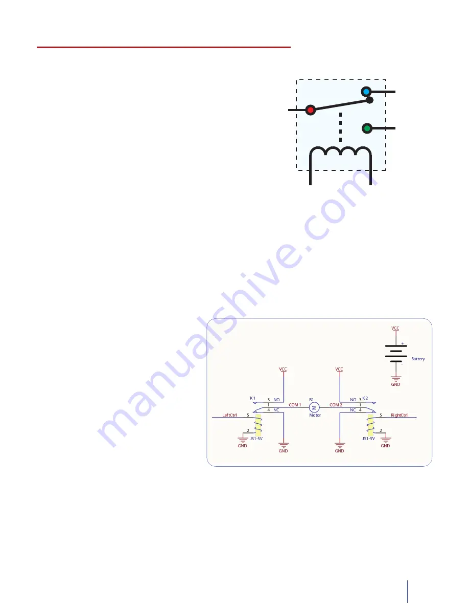
In switch schemes, the number of poles represents the number of common terminals a switch has, and the number
of throws represents the number of switchable terminals that exist for each pole. The relays used in the Dual Relay
Board are SPDT relays: single pole, double throw. The internal construction of this type of relay is depicted in the
diagram above. Many other types of relays exist: SPST, DPDT, and DPST, to name a few.
In an SPDT relay, one of the throw terminals is labelled Normally Closed (NC), and the other is labelled Normally
Open (NO). As the name indicates, the normally closed terminal is the terminal connected to common when the
relay coil is not powered. When the relay coil is energized by the relay control circuit, the electromagnetic field of
the coil forces the switch element inside the relay to break its contact with the normally closed terminal and make
contact with the normally open terminal. The switch element would then connect the normally open terminal and
the common terminal.
Using Relays as an H-Bridge to implement Forward / Reverse
Connect the load to the COM terminals, in this
case the wires of a DC motor. The Normally-
Open (NO) terminals are connected to the
power supply (VCC), and the Normally-Closed
(NC) terminals are connected to the ground
(GND) of the power supply. Connect the
Control pins to a digital output. You can toggle
the corresponding output to switch the relays.
Looking at the diagram, when LeftCtrl is
enabled and RightCtrl is disabled, the current
will flow from the NO terminal of relay K1
through the motor and into the NC terminal of
relay K2. This will cause the motor to rotate in
one direction. Similarily, if LeftCtrl is disabled
and RightCtrl is enabled, the current will flow
from the NO terminal of relay K2 through the
motor and into the NC terminal of relay K1.
This will cause the motor to rotate in the opposite direction. When both LeftCtrl and RightCtrl are disabled, both
ends of the motor will be shorted to ground and no current will flow. When both leftCtrl and RightCtrl are enabled,
both ends of the motor will be shorted to VCC and again, no current will flow.
NC
NO
C
NORMALLY
CLOSED
NORMALLY
OPEN
COMMON


