Mounting and installation instruction
30.06.16
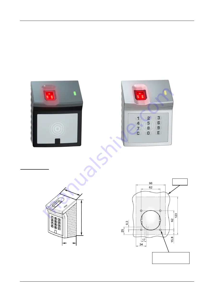
- 7 -
91130.docx
Rev.:1.40
VOXIO Fingerprint
Versions:
VOXIO501 VOXIO502 VOXIO504 VOXIO505
Dimensions
123
96
55
Holes for mounting plate
Wall
Page 1: ...Montage und Installationsanleitung 30 06 16 1 91130 docx Rev 1 40 VOXIO Fingerprint Varianten VOXIO501 VOXIO502 VOXIO504 VOXIO505 Ma e 123 96 55 Befestigungsl cher f r Montageplatte Wand...
Page 2: ...ungsversorgung 10 30V DC interner Verpolungsschutz Maximale Leistungsaufnahme ohne RFID 2 5 W mit RFID 3 5 W Schutzart IP 54 Aufbau Kabelzuf hrung Aufputz von unten Kabelzuf hrung Unterputz durch die...
Page 3: ...Abschirmlitze steckbar Achtung Die steckbaren Anschlussklemmen ST1 ST2 ST13 und ST17 sind in vier unterschiedlichen Farben ausgef hrt Es ist zwingend darauf zu achten dass die jeweilige Klemme auf die...
Page 4: ...die Wand schrauben 4 Abgeschirmtes Kabel auf geeignete L nge zuschneiden Ummantelung entfernen und Abschirmung vorbereiten Kabel unter Kabelschelle klemmen so dass Zugentlastung und Kontaktierung der...
Page 5: ...iv beeinflusst werden Die Leser k nnen sich im Abstand von ca zwei bis dreifacher Lesedistanz noch gegenseitig st ren Energiereiche St rquellen im Bereich der Modulations und Tr gerfrequenzen k nnen d...
Page 6: ...Montage und Installationsanleitung 30 06 16 6 91130 docx Rev 1 40...
Page 7: ...Mounting and installation instruction 30 06 16 7 91130 docx Rev 1 40 VOXIO Fingerprint Versions VOXIO501 VOXIO502 VOXIO504 VOXIO505 Dimensions 123 96 55 Holes for mounting plate Wall...
Page 8: ...y 10 30V DC internal polarity reversal protection Maximum power input without RFID 2 5 W with RFID 3 5 W Protection class IP 54 Construction Cable mounted on the wall with cable entry from below Flush...
Page 9: ...the pin contact strip with the same colour Sabotage detection Optical IR reflection light barrier Sabotage is detected when the reader is removed from the rear wall mounting plate ST17 ST2 ST1 ST13 Co...
Page 10: ...nting plate with suitable screws on the wall 4 Cut the shielded cable to the appropriate length Remove the cable sheath and prepare the cable shielding Clamp the cable under the cable clip so that a s...
Page 11: ...he readers can interfere with each other at a distance of two to three times of the reading distance High energy interference sources in the area of the modulation and carrier frequencies might also d...