background image


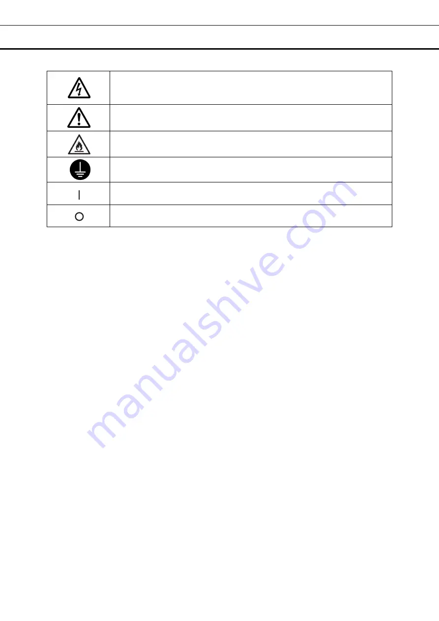
   SYMBOLS ON UNIT 

 
The following symbols are attached to the unit.    The table describes the meaning of the symbols. 


This symbol is attached to covers that access high-voltage electrical components to 
prevent electric shock.  Only a qualified engineer or service personnel should be 
allowed to open these covers. 


This symbol indicates that caution is required.    Refer to product documentation for 
details. 


This symbol indicates Incorrect usage could lead to a fire hazard. 


This symbol indicates an earth. 


This symbol means “ON” for a power switch. 


This symbol means “OFF” for a power switch. 

Summary of Contents for MDF-DU302VX

Page 1: ...X Please read the operating instructions carefully before using this product and keep the operating instructions for future use See page 62 for model number Operating Instructions Ultra Low Temperatur...

Page 2: ...mode 25 Setting key lock 26 Removing key lock 29 ALARM PARAMETERS 30 OPERATION ALARM LOG Setting log interval 32 Displaying operation log 33 Exporting operation log 36 Displaying alarm log 39 Exportin...

Page 3: ...ating instructions are subject to change without notice for improvement of performance or function Contact our sales representative or agent if any page of the operating instructions is lost or the pa...

Page 4: ...are illustrated in the following way WARNING Warning indicates a potentially hazardous situation which if not avoided could result in serious injury or death CAUTION Failure to observe CAUTION signs...

Page 5: ...re flammable or volatile substances are present may cause explosions and or a fire Do not install the unit in a location where corrosive gases such as acids are present Installing the unit in a locati...

Page 6: ...or short circuit if the liquid is spilled Never damage the power supply cord or power supply plug by breaking adapting placing near a source of heat bending with force twisting pulling adding weight...

Page 7: ...t be sure to take precautions to prevent it from falling over Moving the unit with too much force may cause it to fall over possibly resulting in injury A qualified individual must be assigned to supe...

Page 8: ...s in this unit except in a sealed container These may be harmful to your health and may cause corrosion of internal components or electrical parts Check the settings when restarting operation after a...

Page 9: ...onents to prevent electric shock Only a qualified engineer or service personnel should be allowed to open these covers This symbol indicates that caution is required Refer to product documentation for...

Page 10: ...OVERVOLTAGE CATEGORY II Temporary OVERVOLTAGES occurring on the mains supply Applicable pollution degree of the intended environment POLUTION DEGREE 2 in most cases INTENDED USE AND PRECAUTIONS This e...

Page 11: ...11 FREEZER COMPONENTS Main body When an optional backup cooling kit is installed 7 10 17 19 inside 11 15 16 5 14 13 12 18 9 9 Door gasket 4 2 1 Outer door 6 8 20 19 Inside the outer door 3...

Page 12: ...and secure the unit to a wall with a strong rope or chain page 17 11 Power switch This is the power switch of the unit ON l OFF 12 Temperature setting knob TEMP SET It is the knob which adjusts inject...

Page 13: ...the factory page 44 4 Control display The present operation control mode is displayed pages 25 26 Normal control Normal is displayed Eco control ECO is displayed 5 Alarm display pages 47 48 Normal co...

Page 14: ...alarms status or information of the operation monitor system the message on the screen is changeable 10 Menu key Press this key to lead the Menu screen It is possible to set various setting on the Men...

Page 15: ...C Close Open Open Maintain in abnormality COM N O Open Close Close Maintain in abnormality OFF Interlock with Buzzer key COM N C Close Open Close Return to normal COM N O Open Close Open Return to no...

Page 16: ...ambient temperature is subject to sudden changes it will not be possible to achieve a stable cooling performance A flat surface where the floor is also capable of bearing the total combined weight pro...

Page 17: ...dipped in clean water to remove traces of the detergent After this be absolutely sure to wipe the surfaces with a dry cloth allowing the surfaces of the outer cabinet to dry out completely and then p...

Page 18: ...power outlet is not a 3 pin outlet equipped with an earth contact ask a qualified contractor to do the earthing work 5 Setting up the shelves Three shelves are packaged at the bottom of the chamber Se...

Page 19: ...ing the temperature display check that the chamber temperature has cooled to the set temperature Check that the chamber temperature falls to the set temperature when the start up after cleaning mainte...

Page 20: ...he capacity of the battery for power failure alarm is flat during a power failure subsequent operation log data and alarm log data is not saved Operation after recovery from power failure The set valu...

Page 21: ...can be exported 33 35 Data Export Export screen Actual Temp Export Chamber temperature log 36 38 Door Opening Export Door opening log 36 38 Setting Setting Log interval Unique ID 32 33 Alarm Display...

Page 22: ...ow is displayed 2 Press Numeric key or Up Down key to input numerical value and press OK key Key description Numeric key 0 9 Input numerical value Up Down key Increases or decreases the numerical valu...

Page 23: ...elete an alphanumeric character on the left side of the cursor Cancel key Stops inputting on the alphanumeric input box and closes the alphanumeric input window Note While the alphanumeric input windo...

Page 24: ...he display returns to the Menu screen Each parameter setting Temperature Set value of chamber temperature Settable range 90 o C 50 o C Control range 86 o C 50 o C factory setting 80 o C High Alarm Whe...

Page 25: ...en the value of the current chamber temperature is equal to the High Low Alarm set temperature 4 On the Menu screen press Back key to return to the Top screen Setting operation control mode 1 Press Me...

Page 26: ...ressor This unit is required a large electric power at the moment its compressor starts When some units are in a same room set so as to be shifted to each other the compressor delay times to prevent t...

Page 27: ...1 is saved and Confirm dialog box is displayed Yes On the Key Lock screen it is possible to set the release password 2 No The display returns to the Menu screen Select No when it is no need to set the...

Page 28: ...ease password of Key Lock properly Operation for Keylock ON When pressing Menu key Password input box is displayed and input of the release password of Key Lock is required If two passwords are regist...

Page 29: ...nd press OK key to lead the Menu screen 3 Press Key Lock key to lead the Key Lock screen 4 On the Key Lock screen by holding Key Lock slide key and sliding to the left change to OFF Press Apply key to...

Page 30: ...30 ALARM PARAMETERS 1 Press Menu key to lead the Menu screen 2 Press Tools key to lead the Tools screen 3 Press Alarm Setting key to lead the Alarm Setting screen...

Page 31: ...sounds again when the alarm state still continues after the ring back set time passed even though the alarm buzzer was stopped by pressing Buzzer key By holding and sliding Ring Back slide key to the...

Page 32: ...ose state of door Note When the battery switch for power failure alarm is ON operation log is saved during a power failure Use the following procedure to set the log interval interval of acquiring the...

Page 33: ...le to register 8 digit alphanumeric characters as the Unique ID page 38 Note Relation between log interval and the estimated amount of data that can be saved Log interval 2 minutes Approx 46 days Log...

Page 34: ...how key after pressing the item you want to display graphically the graph of each operation log is displayed Actual Temp Chamber temperature log graph Go to procedure 6 Door Opening Open close state o...

Page 35: ...ted into the USB port 8 Insert the USB memory into the USB port Note It is not possible to use a USB memory with security functions that requires entering password 9 Press Export key 10 When the expor...

Page 36: ...to the USB memory inserted into the USB port 1 Insert the USB memory into the USB port Note It is not possible to use a USB memory with security functions that requires entering password 2 Press Menu...

Page 37: ...ed during a month Refer to page 44 for the procedure of setting time 6 On the Export screen select the type of operation log data you want to export To export all types of operation log data press All...

Page 38: ...t in CSV format The exported file name is in date 8 digits type of data format e g When exporting all types of data using All from Jan 1st 2017 to Oct 1st 2017 20170101 20171001_AllCh csv 20170101 201...

Page 39: ...the oldest alarm log is deleted and then overwritten When the battery switch for power failure alarm is ON operation log is saved during a power failure Alarm log saved in the freezer can be displaye...

Page 40: ...e 1 day 45 days Note The error of about 1 minute may be observed during 1 month Refer to page 44 for the procedure of setting time Press Back key to return to the Log screen Press Top key to return to...

Page 41: ...serted in the USB port by CSV format 1 Insert a USB memory in the USB port Note It is not possible to use a USB memory with security functions that requires entering password 2 Press Menu key to lead...

Page 42: ...button and input days Settable range 1 day 45 days Note The error of about 1 minute may be observed during 1 month Refer to page 44 for the procedure of setting time 6 Press Export key Note When USB m...

Page 43: ...A log folder is created in a USB memory and an exported data file is saved in the log folder by CSV format Exported file name The first date during exported period 8 digits the last date 8 digits Ala...

Page 44: ...ey to lead the Date Time screen 4 On the Date Time screen input the present date and time Press Apply key to save the input value The display returns to the Tools screen Note 24 hour clock It is recom...

Page 45: ...reen 2 Press Tools key to lead the Tools screen 3 Press Brightness Sleep key to lead the Brightness Sleep screen 4 On the Brightness Sleep screen each setting of brightness and sleep is available Pres...

Page 46: ...right the Sleep function is turned to ON Input the set value of time to change the Sleep state Settable range 1 minute 5 minutes factory setting 2 minutes Note It is not possible to operate any key i...

Page 47: ...sor A does not start up Or diagnostic sensor failure A Compressor Start up failure Warning Temp Control Risk W12 Compressor B Control Failure Compressor B does not start up Or diagnostic sensor failur...

Page 48: ...Diagnostic sensor failure Thermocouple A Abnormality Status Temp Under Control S09 Thermocouple B Abnormal Diagnostic sensor failure Thermocouple B Abnormality Status Temp Under Control S14 Ambient T...

Page 49: ...m Remote Alarm setting Ring Back setting Buzzer from unit Remote Alarm setting When pressing Buzzer key When the Ring Back set time passes ON Non interlock with Buzzer key ON OFF Alarm is canceled OFF...

Page 50: ...ed surfaces or cause perishing of plastic and rubber components Moreover do not wipe plastic and rubber components with a volatile material In order to maintain the unit s intended level of performanc...

Page 51: ...efrigerated by liquid carbon dioxide or dry ice 3 Turn off the power switch and battery switch of the freezer 4 Open the outer door and inner door Remove the inner door by lifting up as shown in the f...

Page 52: ...Always follow the procedure for recycling Replacing the battery for backup cooling kit Replace the battery for backup cooling kit about every 3 years Contact our sales representative or agent for the...

Page 53: ...rial has been put in the chamber The door is frequently opened The set value of the chamber temperature is lower than 86 o C The temperature settable range is between 90 o C 50 o C However the tempera...

Page 54: ...for an extended period ensure that children do not have access and doors cannot be closed completely The disposal of the unit should be accomplished by appropriate personnel Always remove doors to pre...

Page 55: ...ion und L nder mit Recyclingsystemen Dieses Symbol auf den Produkten der Verpackung und oder den Begleitdokumenten bedeutet dass gebrauchte elektrische und elektronische Produkte sowie Batterien nicht...

Page 56: ...ive au produit chimique concern Spanish Eliminaci n de Aparatos Viejos y de Pilas y Bater as Solamente para la Uni n Europea y pa ses con sistemas de reciclado Estos s mbolos en los productos su embal...

Page 57: ...Neste caso estar em conformidade com o estabelecido na Diretiva referente aos produtos qu micos em causa Italian Smaltimento di vecchie apparecchiature e batterie usate Solo per Unione Europea e Nazi...

Page 58: ...l Onderstaand symbool Dit symbool kan in combinatie met een chemisch symbool gebruikt worden In dit geval volstaan de eisen die zijn vastgesteld in de richtlijnen van de desbetreffende chemische stof...

Page 59: ...turn changeable Recording paper Strip type Circular type Power source Dry cell Supplied from the unit For the installation of temperature recorder MTR 85H an optional recorder fixing MDF S3085 and re...

Page 60: ...ON OFF type the actual injection temperature deviates from the injection set temperature Note Set the injection set temperature of the backup cooling kit to 10 o C higher than the set temperature Othe...

Page 61: ...ture display LCD Digital display Thermal sensor Platinum resistance Pt 1000 Alarm High Alarm Low Alarm Power failure alarm Door alarm Remote alarm Remote alarm contact Allowable contact capacity DC 30...

Page 62: ...temperature 30 o C no load Rated voltage AC 220 V 230 V 240 V Rated frequency 50 Hz Rated power consumption 645 W 655 W 690 W Max 795 W 810 W 845 W Noise level 52 dB A background noise 20 dB Maximum p...

Page 63: ...unit Unit interior No contamination Decontaminated Contaminated Others 3 Instructions for safe repair maintenance disposal of the unit a The unit is safe to work on b There is some danger see below Pr...

Page 64: ...rating Instructions Printed in Japan LDCL046900 0 S0418 0 2018 04 01 1 1 1 Sakada Oizumi machi Ora gun Gunma 370 0596 Japan EU countries only PHC Corporation 2018 Nijverheidsweg 120 4879 AZ Etten Leur...

Reviews: