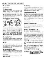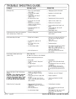
To Assemble:
See instructions, page 3.
To Adjust Handle:
The handle adjustment is controlled by a “star latch” located at the rear of the
machine near the bottom of the handle pipe. To release, turn the knob
counter-clockwise or by applying foot pressure to the lower portion of the
knob. When a convenient handle location for machine operation has been
found, lock the handle in place by turning the star knob clockwise to tighten.
When transporting the machine or attaching brush/pad be sure the handle is
LOCKED in the upright position. NEVER TURN ON THE MACHINE WITH
HANDLE IN THE UPRIGHTLOCKED POSITION.
Brush Attachment and Removal:
Figure 1
To attach brush
To remove brush
With cable unplugged,
LOCK
handle in upright position and tilt machine back
on the handle until the underside of the machine is fully exposed. Select the
desired brush, scrub or drive, and position the three slots of the clutch plate
over the three lugs of the gearbox. Turn the brush as shown in Fig. 1 as far
as it will go. The brush is now seated in ready-to-use position.
TO
REMOVE BRUSH
, disengage clutch plate slots from the gear box by turn-
ing clockwise.
DO NOT OPERATE THIS MACHINE WITHOUT
SCRUB BRUSH OR DRIVE BRUSH AND PAD IN PLACE.
NEVER POSITION RUNNING MACHINE OVER AN UNAT-
TACHED BRUSH.
To Attach a Pad:
If a pad is to be used, a pad drive (not a scrubbing brush) must first be installed
as shown in the preceding paragraph. Place the pad on the brush bristles and
push the pad firmly onto the brush. Be sure the pad is properly centered on
the brush.
To Start:
With the power cable plugged into a proper outlet, release safety latch and
squeeze the switch bar beneath the handle grips. This machine is equipped
with a mechanical safety lockout on the left handle bar to prevent accidental
startup. The lockout must be pushed forward with the operators left thumb
before the switch bar can be moved.
To Operate Safety Latch:
The operator must manually rotate the latch with the left thumb before the trig-
ger can be depressed to start brush rotation. When the trigger is released, the
safety latch snaps back into position. This will prevent accidental machine
startup.
CAUTION:
Machine will immediately veer to one side. Be
prepared to control action.
To Operate:
This machine is designed to move from side to side. To guide right, raise the
handle slightly. The higher the handle is raised, the faster the machine will
move to the right. Conversely, to guide left, lower the handle. The more the
handle is lowered, the faster the machine will move to the left. WARNING:
DO NOT LEAVE A PLUGGED IN MACHINE UNATTENDED.
Care and Maintenance:
This machine will afford you many years of trouble free service provided it is
given proper care. Throwing, dropping, bumping across thresholds and other
misuse may result in a damaged unit and invalidate the warranty. For best
results, use a clean pad and change frequently as pad loads up. When stor-
ing your floor machine, always remove the pad and brush.
Pads can be cleaned by washing in warm water and a mild detergent, rinsing,
and hanging up to dry.
Do not lubricate this machine. Lubrication has been applied and permanent-
ly sealed at the factory.
Machine Serial Number:
To obtain qualified service, you may need the serial number of the machine
when requesting service under warranty or when ordering certain parts. The
serial number is found on the data plate located on the machine chassis, not
on the motor data plate.
Brush, Floor Machine and
Burnisher Size Determination:
The numerals contained within the machine model designation indicate the
nominal machine size. In all cases the nominal size is determined by the full
spread of the bristles of a long bristle scrub brush on a floor surface when
under the weight of a floor machine. The spread of a short or stiff bristle brush
will be somewhat less. The brush block diameter will always be two (2) inch-
es less than the nominal brush size, i.e., a 20” brush will have an 18” diame-
ter block. In like manner, the opening on the underside of a machine will be
about 1 to 1.5 inches smaller than the nominal machine size, i.e., a 20”
machine will have an opening of about 18.5 to 19 inches in diameter.
Warning:
Connect power cord only to an electrical
supply the same as shown on the motor data plate.
Connecting to the wrong voltage supply will result in dam-
age not covered by warranty and may cause personal
injury.
NOTE: 220 volt machines are shipped without a plug on the
end of the power cord due to the many styles of 220 volt
plugs in use. Have a qualified electrician attach the proper
plug for your location to the cord end.
Warning of Potential Injury:
Moving Parts - To reduce the risk of injury, unplug before
servicing.
Fire or Explosion - Do not operate machine in the vicinity of
flammable or explosive vapors. Never use
flammable liquid to clean a floor.
ABOUT THE FLOOR MACHINE


