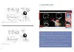
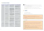
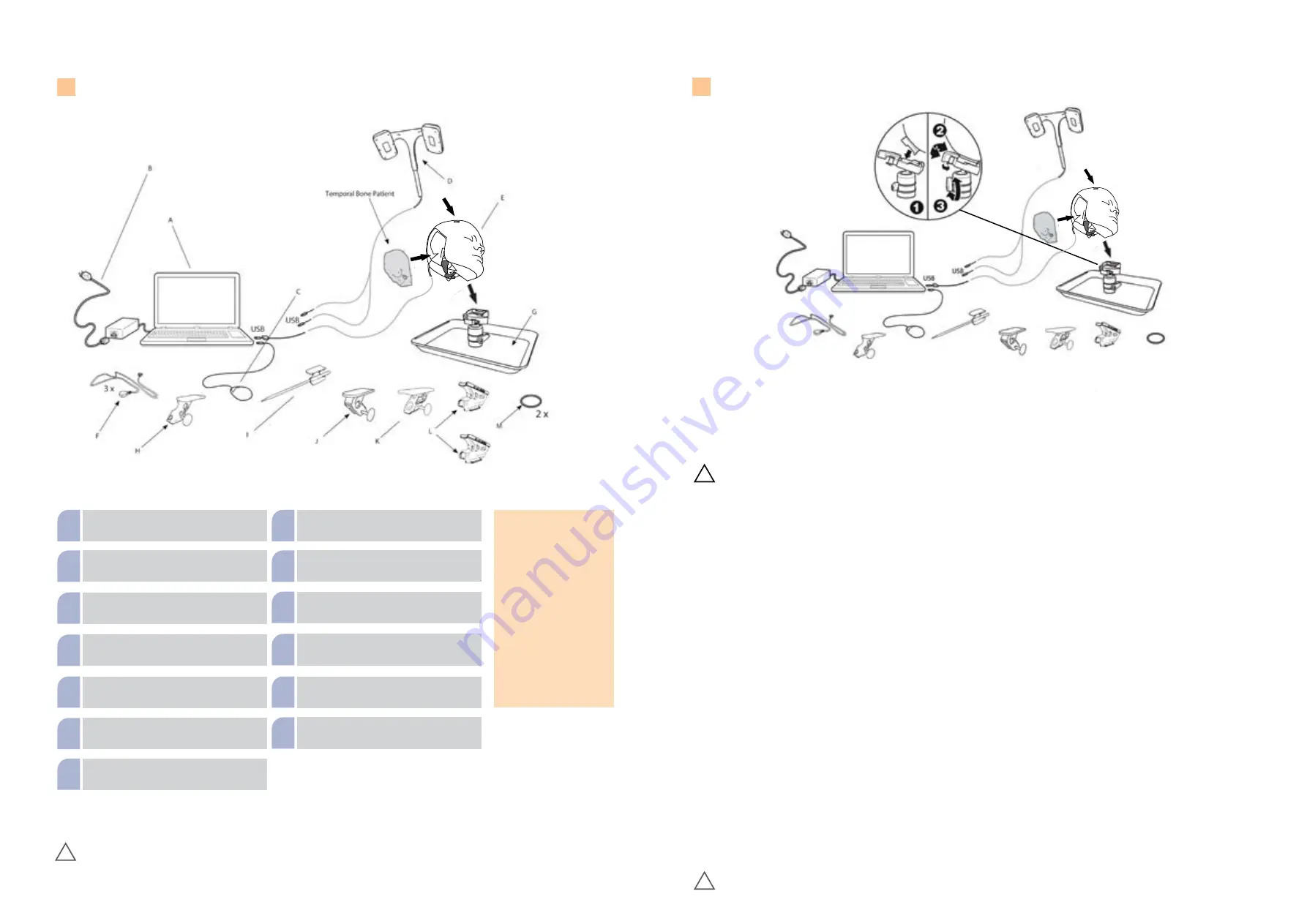
PHACON S-00024 User Manual Download Page 5

9

8

TRAINER COMPONENTS

Laptop with navigation software

A

Power supply suitable for the 

voltage of the country

B

Mouse

C

Navigation camera

D

Temporal bone head

E

Ground cable (3x)

F

Holder Tray with adjustable head fixation

G

Instrument tracker for a ballprobe

H

Pointer

I

Instrument tracker suction device

J

Instrument tracker for blakesley or trucut

K

3 x Instrument tracker for different drills

L

O-Ring for fixation of the drill tracker

M

NOTE

Every PHACON Temporal 

Bone Trainer with naviga-

tion contains a navigation 

camera which is labeled 

with a part number at the 

side surface (SCXXXXX). The 

belonging trainer laptop 

shows the same number 

labeled on its underside. 

If you are using more than 

one trainer, please make 

sure to use the right combi-

nation of camera and laptop 

(equal part number).

!

Warnings:

 Injury through clamp! When the head is placed on the support tray and when the patient is inserted into the head, there is the 

danger of being trapped the fingers. Injury through stabbing! The included pointer can lead to serious or fatal injuries if used improperly.
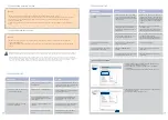
INSTRUCTIONS

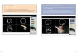
PREPARE THE TRAINER FOR USE

Set Up the Head 

(Figure 1)

              WARNINGS:

• ALWAYS place the power cord away from personnel traffic areas to 

eliminate a trip hazard. NEVER place the power cord near to water or 

liquids to prevent a shock hazard.

• DO NOT expose any electronic component of this system to fluid, ex-

cessive humidity, or heat.

CAUTIONS:

• ALWAYS place cables and connectors away from any possible crush 

hazard.

• ALWAYS connect a suction canister and apply a source of vacuum to 

the head before operating the system to facilitate the removal of debris 

during training.

NOTES:

• The use of irrigation is recommended during the drilling and/or milling 

procedure.

• Make sure the head with tray and the laptop computer are optimally 

placed to facilitate easy access.

1. Install the head onto the ball joint plate until it snaps into place.*

2. Rotate the head lever and head lever lock to fasten the head to the 

ball-joint mounting plate.

3. Rotate the head to the desired position. Rotate the ball-joint lever/

lock to secure the head in place.

4. Connect the camera USB extension cord to the USB cable plug of the

navigation camera.

5. Install the navigation camera into the navigation camera cradle of the 

head and attach the navigation camera.

6. Connect a suction tube between the suction port of the head and a 

facility suction canister.

7. Connect a suction tube between the suction canister and a facility vac-

uum source.

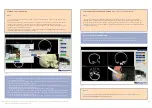
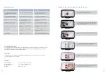
Install the Temporal Bone Insert and Connect the Surgical

Instruments


(Figure 2)

NOTE:

 To install or remove the temporal bone insert, always orient the 

lever in a downward position.

1. Install the temporal bone insert into the temporal bone insert cavity 

of the head.*

2. Rotate the T-Bone insert lever to secure the temporal bone insert to 

the head.

NOTE:

 The use of a manual instrument is optional.

3. Place the manual instrument tracker onto a manual instrument (for-

ceps, for example). Secure the manual instrument tracker to the manual 

instrument by hand tightening the thumb screw.*

4. Apply the magnet of the ground cable from the head to the manual 

instrument.

5. Place the drill tracker onto the housing of the drill. Fasten the drill 

tracker to the body of the drill using the O-ring.*

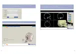
Connect the Laptop Computer*

 (Figure 3)

1. Connect the USB cable from the head, the navigation camera, and the 

laptop computer mouse to a USB port on the laptop computer.

2. Connect the plug of the laptop computer power adapter into the pow-

er port of the laptop computer.

3. Connect the power cord between the laptop computer power adapter 

and the facility power source.

4. Press the power button to turn the laptop computer on.

NOTE:

 See the instructions for use supplied with the laptop computer.

!

Figure 1

Set Up the Head

!

*Warnings

: Injury through clamp! When the head is placed on the ball-and-socket joint, there is a risk that the fingers will get caught. When 

you insert the camera into the head, you could pinch your fingers. There is a risk of tripping due to loose cables and a risk of strangulation 

due to cables.

3 x

Summary of Contents for S-00024

Page 1: ...USER MANUAL PHACON TEMPORAL BONE TRAINER BILATERAL...

Page 2: ...DISCOVER THE INTRODUCTION INTO THE PHACON TRAINER your laptop with navigation software your tracking camera your holder tray with head your trackers your patient your pointer...

Page 3: ...FORMATION 8 TRAINER COMPONENTS 9 INSTRUCTIONS 11 LAPTOP DISPLAY SCREEN 12 BUTTONS 13 OPERATE THE TRAINER 15 Enter the application 18 Perform setup for navigation 19 Perform patient calibration 20 Perf...

Page 4: ...rument tracker set for ENT surgery RE 00005 DESCRIPTION REF 3 instrument linkage cable RE 00009 1 notebook with PHACON simulation software RE 00011 1 USB 3 0 hub ZS 00006 1 computer mouse RE 00012 1 p...

Page 5: ...d lever lock to fasten the head to the ball joint mounting plate 3 Rotate the head to the desired position Rotate the ball joint lever lock to secure the head in place 4 Connect the camera USB extensi...

Page 6: ...pecific panel type C Camera Line of Sight Used to display the image within the navigation camera s line of sight D Simulation Time Used to display the start time of the simulation the current time and...

Page 7: ...e software German English Reset the default settings for brightness contrast and slice position in the 4 windowpane in the simulation mode Close and exit the program End the SIMULATION or training ses...

Page 8: ...click on the PHACON Trainer icon located on the laptop computer desktop to log into the training program ENTER THE APPLICATION 2 Type in your user name and password If you do not have an account you...

Page 9: ...fields are optional 4 From the MAIN MENU screen click the SIMULATION button Fig 3 Fig 3 Click on the SETUP button to perform instrument and patient calibration for optimal navigation results See To P...

Page 10: ...of the pointer drill or manual instrument The five calibration points are visible on the Temporal Bone Patient and within the 3 D windowpane during calibration Sequence numbers and a progress bar are...

Page 11: ...atient Make sure the tracking shapes are facing the camera and are within the camera line of sight 3 After visual and audible feedback indicates successful data acq uisition change the angle of the to...

Page 12: ...middle mouse button may also be used When using navigation the CT image slice is selected automatically based on the tip location of the pointer drill or manual instrument To view different slices of...

Page 13: ...he 3 D windowpane Fig 11 ADJUST THE OPACITY VALUE OF AN ANATOMICAL STRUCTURE The opacity of a specific anatomical structure may be changed to provide better visualization within and behind the Patient...

Page 14: ...ING which indicates that the recording has been started 2 To end the recording clickon the button RECORDING 3 To save the recorded video click on the CLASSIC but ton to change to the simulation mode N...

Page 15: ...ND button to end the training session and return to the MAIN MENU screen END THE SIMULATION OR TRAINING SESSION VIEW THE TRAINING SESSION RESULTS 1 From the MAIN MENU screen click on the RESU LTS butt...

Page 16: ...r group results Fig 20 1 Click on the ADD GRAPH button to compare your results with other group results Fig 20 2 From the COMPARISON WITH OTHER GROUPS dialog box clickon the GROUP drop down list and s...

Page 17: ...thin the head using a dry brush and an external vacuum source Make sure the spillways are clear to allow water to low freely during the use of irrigation 5 Wipe all the surfaces of the head including...

Page 18: ...s in the left column of the NVIDIA Control Panel 3 In the Global Settings klick on High performance NVIDIA processor 4 If the Apply button does not appear please select High performance NVIDIA process...

Page 19: ...e head in the free space on the top of the holder tray Now you can close the case lid top gently TRAINER STORAGE HOW TO PACK THE TRANSPORT CASE MESSAGE CAUSE ACTION The LOGIN password or user name is...

Page 20: ...ed with accessories not manufactured by PHACON or if repairs are performed by any party other than authorized PHACON repair personnel Except as set forth above phacon makes no warranties with respect...

Page 21: ...Germany tel 49 0 3 41 47 83 97 32 fax 49 0 3 41 47 83 91 74 www phacon de email info phacon us 4470 Chamblee Dunwoody Rd Suite 463 Dunwoody GA 30338 USA tel 1 833 2 PHACON 2 742266 fax 470 243 0494 w...

Reviews: