Pfeuffer Sample cleaner MLN Operating Instructions Manual Download Page 23

Operation 


Revision 3 | Operating instructions sample cleaner MLN  

23 | 38 


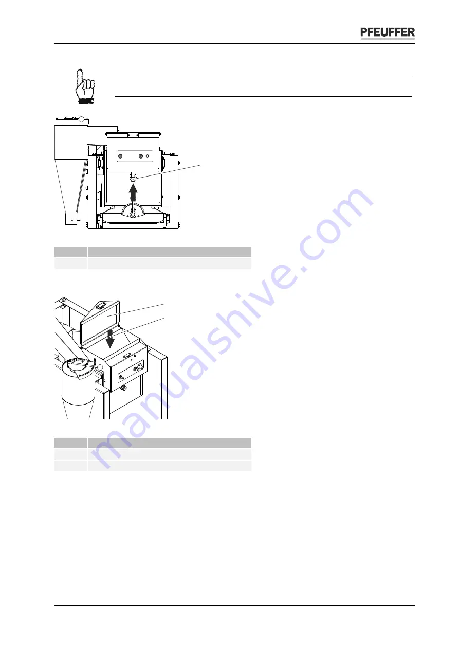
Close the deawner bottom by pressing the locking lever.


The deawner bottom must be manually closed again after every cleaning process! 


Figure 12: Locking lever for deawner bottom 

Item 

Name 

Locking lever 


Open the cover of the filling container and pour the sample in the deawner. 


Figure 13: Fill in the sample 

Item 

Name 

Filler cap opened 

Sample 


Set the deawner time on the potentiometer. 


Close the filler cap and the door of the sample cleaner. 


Switch the control switch 

ON

The sample cleaner starts. 

o


A limit switch system is integrated into the filler cap. 

The deawner will start only if the filler cap is closed. 


1

2

1

Summary of Contents for Sample cleaner MLN

Page 1: ...uffer GmbH Flugplatzstra e 70 97318 Kitzingen GERMANY Phone 49 9321 9369 0 Fax 49 9321 9369 50 info pfeuffer com Revision 3 15 12 2020 www pfeuffer com Translation of the original operating instructio...

Page 2: ...ment is not allowed to be communicated or duplicated utilized without express permission which also applies to communicating its content Offenders are liable to the payment of damages All rights reser...

Page 3: ...with the machine 10 2 4 Operating and maintenance personnel 11 2 5 Safety measures to be implemented by the operating company 11 2 6 General safety instructions 12 2 7 Safety tests 13 2 8 Residual haz...

Page 4: ...sieve 26 7 4 2 Bottom sieve sand sieve 27 7 5 Recommended sieves and settings 28 8 Maintenance and cleaning 29 8 1 Cleaning 29 8 1 1 Motor 29 8 1 2 Deawner 30 8 2 Lubrication 31 8 3 Inspection interva...

Page 5: ...ufacturer shall not be liable for the resulting damage Damage caused by such an unintended use is at the sole risk of the operator The machine is allowed to be operated only if it is ensured that all...

Page 6: ...Machine DIN EN ISO 12100 2010 Safety of machinery General principles for design Risk assessment and risk reduction DIN EN 60204 1 2006 Safety of machinery electrical equipment of machines part 1 Gener...

Page 7: ...gainst the danger DANGER This is a warning about a highly dangerous situation that will lead to serious or fatal injuries WARNING This is a warning about a dangerous situation that may result in serio...

Page 8: ...OTICE It is strictly forbidden to disable the safety devices or to change their mode of operation 2 1 Installed safety systems The installed safety systems must be checked with corresponding test meth...

Page 9: ...to secure the deawner against unauthorised access during operation Locking latch at filler cap The deawner can be started only if the filler cap is closed Test Interval Method m VI 2 1 4 Protective ca...

Page 10: ...casing 9 Cyclone 2 3 Operating and hazard areas associated with the machine Operating area Ensure a sufficient working height depending on the body size of the operating personnel of approx 60 65 cm F...

Page 11: ...5 Safety measures to be implemented by the operating company It is noted that the operating company trains the operating and maintenance personnel with regard to the safety devices of the sample clean...

Page 12: ...tion Cleaning cleaning agents and disposal Hazardous substances in Germany the technical rules for hazardous substances TRGS 555 apply Environmental protection regulations Electrical connections The s...

Page 13: ...n primarily takes place in automatic mode Pay attention to electrical hazards in case of all tasks that are to be carried out vis a vis electrically operated components Be mindful of crushing hazards...

Page 14: ...on instructions Executed as per VDE 3 3 General information Temperature 5 C to 40 C Humidity 20 80 non condensing Acoustic level LPA 82 dB A as per measurement report 4 Delivery transport and storage...

Page 15: ...be transported by skilled personnel only and in accordance with the local conditions and if applicable the information on the packaging material Sample cleaner MLN is supplied to the installation loca...

Page 16: ...llation site using a pushcart Packaging for return delivery If possible use the original packaging and original packaging material If both are unavailable engage a packaging company with skilled perso...

Page 17: ...lacing a suction hood over the air outlet of the cyclone The distance between the air outlet and the suction hood must be at least 400 mm so that the aspiration effect is not affected CAUTION Dust war...

Page 18: ...ottom of the deawner 8 Potentiometer Deawner time 9 Tension springs on sieving tray 10 Collection pan for cleaned sample 11 Collection pan for sand weeds and coarse dirt particles 12 V ribbed belt Fan...

Page 19: ...s closed The machine starts when you close the cover of the filling container and switch the control switch to ON The deawner base automatically opens after a period of time specified on the potentiom...

Page 20: ...ents Item Name 1 Air regulation 2 ON OFF control switch 3 Control switch for manually opening the deawner base 4 Potentiometer 5 Locking lever for deawner base 6 Outlet regulation 7 1 1 Potentiometer...

Page 21: ...to guarantee an even distribution of the grain across the sieves 1 smallest opening gap more flow time 15 largest opening gap short flow time Make sure that different opening gaps are selected for di...

Page 22: ...hazardous levels of Mycotoxins can be present in this dust Check whether inhaling large quantities might lead to irritation or illnesses of the respiratory passages and if so then take appropriate me...

Page 23: ...m Item Name 1 Locking lever Open the cover of the filling container and pour the sample in the deawner Figure 13 Fill in the sample Item Name 1 Filler cap opened 2 Sample Set the deawner time on the p...

Page 24: ...ther the sieves are free after the cleaning process ends If grains are stuck you can remove them by slightly knocking with your fingers Weigh the cleaned sample again This way you can determine the wa...

Page 25: ...rder to attain unrestricted space for the sieve changing operation rotate the springs in the direction of the respective side wall The sieves are now ready to be changed Figure 14 Tension springs on s...

Page 26: ...the mounting position refer to figure 15 Figure 15 Straw sieve mounting position Dimensions 300x350 mm Item Name 1 Engraved number 2 Surface not stamped The plastic sheet on the sieve holder must pull...

Page 27: ...lide the new sieve on the sieving tray till the stop It might have to be slightly lifted Pay attention to the mounting position refer to figure 17 Figure 17 Sand sieve mounting position Dimensions 300...

Page 28: ...mm 3 5 x 20 mm 15 10 12 Soybeans 8 0 mm 9 0 mm 2 5 x 20 mm 15 8 10 Sunflower 11 0 mm 12 0 mm 2 0 x 20 mm 2 5 x 20 mm 7 9 8 10 Key round hole x slot or The specified settings and sieves are recommende...

Page 29: ...tion to local statutory accident prevention regulations Time related factors associated with the execution of the cleansing related and maintenance activities are calculated for single shift operation...

Page 30: ...r approximately 60 s If it is possible to clean the deawner bottom by hand you must remove the filling container CAUTION The deawner could start and lead to hand injuries Pull the mains plug Undo both...

Page 31: ...lling container 8 2 Lubrication Maintenance free bearings are used in sample cleaner MLN Lubrication is not necessary 8 3 Inspection interval and functional test Assembly Interval during single shift...

Page 32: ...refer to list of spare parts Chapter 10 Worn out parts must be replaced by skilled personnel only m 8 5 Check After the work has finished check The completeness of the work carried out That there are...

Page 33: ...ow any function System voltage not available Control switch ON OFF remains at OFF Internal fuse defective Get the system voltage checked and activated by an electrically skilled person Switch the cont...

Page 34: ...gled with rubber bushes 2350 0256 Lever switch Long straight with rubber bushes 2350 0365 Rubber bush for eccentric axle 3135 1740 Other spare and replacement parts are available on request A complete...

Page 35: ...hecking the nominal hole widths 1249 0020 11 3 Sieves Top sieve straw sieve 300 x 350 mm Item number 2 8 mm 3115 5067 3 0 mm 3115 5070 8 0 mm 3115 5118 9 0 mm 3115 5124 10 0 mm 3115 5127 11 0 mm 3115...

Page 36: ...2 19 EU Special waste Oil cleaning agents contaminated cleaning tools brush rags etc must be disposed of according to the local regulations and in accordance with the notes in the manufacturers safety...

Page 37: ...f perforated metal plate Test process Figure 22 Diagram for selecting the hole widths to be tested Select about 40 sieve holes see diagram for 2 5 mm sieve with 29x11 holes 44 selected Position the si...

Page 38: ...sieves Technical requirements and testing Part 2 Test sieves of perforated metal plate Nominal hole width as embossed mm specified tolerance mm Actual hole widths 1 2 3 4 5 6 7 8 9 10 11 12 13 14 15...

Reviews: