Adjustment
26
1
.06
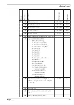
Adjusting the thread trimmer -900/81
1
.06.01
Resting position of the roller lever / radial position of the control cam
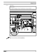
Requirement
When the thread trimmer attachment is at rest lever
1.
7
should fi t closely to plunger
5
and the roller on roller lever
4
should be
0
.
3mm
away from control cam
1
.
When thread lever at t.d.c. (handwheel position
2.
53
°) the control cam
1
should have
just bought roller lever
4
to rest.
Create a distance of
●
50
mm
between the highest point of control cam
1
(screws
2
) and
collar
3
.
Turn the handwheel in the direction of rotation until the highest point of control cam
●
1
is
opposite roller
4
.
Ensure that plunger
●
5
is at the leftmost position, move magnet
6
(two screws) according
to requirement
1
.
Turn control cam
●
1
(screws
4
) according to requirement
2
.
Fig. 1 - 20
2
6
0,3 mm
4
1
7
3
5
50 mm
Summary of Contents for POWERline 2591 ME
Page 44: ...44 Circuit diagrams ...
Page 45: ...45 Circuit diagrams ...
Page 46: ...46 Circuit diagrams ...
Page 47: ...47 Circuit diagrams ...


