


42
Petters Ltd or their agents. Do not attempt to clean the element.
(c) To replace the element
(i) Generally reverse the instructions for removal making sure that
the element seal is in good condition.
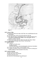
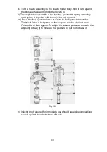
71. To clean fuel filter (separately mounted)
(a) Unscrew the clamp bolt at the centre of the filter bowl and withdraw the
bowl complete with element.
(b) Thoroughly clean out the bowl and examine the joint ring.
(c) If the element shows a large deposit of dirt. fit a new element.
obtainable from Petters Ltd or their agents. Do not attempt to clean the
element.
(d) It is advisable to fit a new joint ring when the element is changed.
(e) Reassemble the filter
(f) Bleed the fuel system.
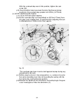
72. To remove fuel injection pump
(a) Drain the fuel tank and remove.
(b) Remove the tank-to-pump and pump-to-injector fuel pipes.
(c) Remove the pump. noting the number and total thickness of shims
between the fuel pump and crankcase.
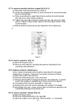
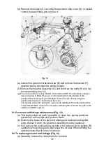
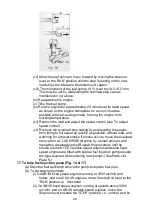
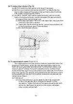
73. To dismantle fuel injection pump (Fig. 14)
NOTE: Fuel injection pumps fitted to all variable speed engines are
subjected to special calibration by the manufacturers and only the delivery
side may be dismantled The pump/control side must NOT be dismantled
and should be returned to the manufacturers or to Petters Ltd or their
agents for servicing.
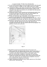
(a) Delivery side
(i) Thoroughly clean the exterior of the pump.
(ii) Unscrew the delivery union body (A), lift out the delivery valve
spring (B) and the delivery valve (C).
(iii) Withdraw the delivery valve seat (D). the joint (E) and sealing
ring (F).
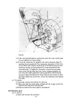
(b) Pump/control side (fixed speed engine only)
(i) Rotate the circlip(G) in its groove until the dowel (H) is between
the ends of the circlip.
(ii) Press down the tappet and roller assembly against the spring
pressure and shake out the dowel (H)
(iii) Remove the tappet (J) together with the roller and roller pin.
Note the number and thickness of the calibrating shims (K)
between the tappet and the lower spring plate (L)
(iv)
Remove the lower spring plate (L). the plunger (M) and the
plunger spring (N). Note the assembly mark on the plunger arm
farthest from the rack (P).
(v)
Remove the upper spring plate (R) and the pinion (S). Note the
assembly marks on one tooth of the pinion (S) and on the rack
(P). Note also the relative position of the 'STOP' mark and arrow
on the rack before sliding out the rack from the pump body.


