background image


e bunt.doc 

Rev. 14.06.2010 

Seite / 

Page 

 37 / 40 


Perrot REGNERBAU CALW GmbH

     Industriestraße 19-27  /  D-75382 Althengstett / Germany 

                                                                     Telefon : 0049-7051-162-0 / Fax : 0049-7051-162–133 

     E-mail :  [email protected]


 / E-mail Konstruktion : [email protected] 


9.2


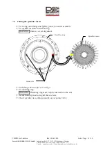
Fitting the control unit 


œ


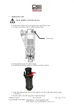
When buying a replacement, the control unit is supplied with plug-and-socket 
connections. Push hoses into plug-in nozzles as far as they will go and ensure that the 
mounting ring springs back 

WARNING:    Please ensure that the hoses are fitted in the correct position. Otherwise the   


sprinkler will not work. 

œ


Screw in coil. 

œ


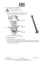
Clip control unit into protective casing. 

œ


Secure housing cover using all three screws. 

œ


Check sprinkler is working properly as per points 5b - 5e. 


10


Removal / fitting of manual opening and pressure regulating inserts 


Ensure sprinkler is not under pressure. 


10.1


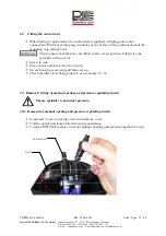
Removal of manual opening and pressure regulating inserts 


œ


Loosen all 3 cover-securing screws and remove cover. 

œ


Unclip control unit from protective casing and lift up. 

œ


Using an SW19 flat spanner, twist out manual opening and pressure regulator screws. 


Coil

Control unit 

Summary of Contents for Hydra L

Page 1: ...U CALW GmbH Industriestra e 19 27 D 75382 Althengstett Germany Telefon 0049 7051 162 0 Fax 0049 7051 162 133 E mail perrot perrot de E mail Konstruktion technik perrot de Bedienungsanleitung Operating...

Page 2: ...ETRIEBNAHME 6 5 2 WINTERFESTMACHUNG 6 6 SEKTOR EINSTELLEN 7 7 D SE TAUSCHEN 9 7 1 EINSTELLEN DER EINLAUFD SE 11 7 2 EINBAU REGNEREINSATZ 12 8 AUSBAU EINBAU VENTILEINSATZ 13 8 1 AUSBAU DES VENTILS 13 8...

Page 3: ...erheitshinweise zu beachten sondern auch die in den anderen Abschnitten eingef gten speziellen Sicherheitshinweise 1 1 Kennzeichnung von Hinweisen in der Betriebsanleitung Die in dieser Betriebsanleit...

Page 4: ...de E mail Konstruktion technik perrot de 2 Beschreibung Draufsicht Einstell schraube linker Anschlag Einstell schraube rechter Anschlag Deckel befestings schraube Deckel befestings schraube Deckel bef...

Page 5: ...n dass die Markierung in die Flucht von der linken Seite des Beregnungssektors zeigt 4 Sonderwerkzeuge Schl ssel f r Grobfilter Hydra L S Grobfilter herausschrauben RZG2 14130 Sicherungshalter f r Reg...

Page 6: ...it Hand ffnung ffnen in dem die Schraube f r Hand ffnung in die Zwischenstellung von AUTO und OFF gebracht wird ca 1Umdrehung Regnerkopf steigt auf und beginnt sich zu drehen Nicht in Richtung der D s...

Page 7: ...y Telefon 0049 7051 162 0 Fax 0049 7051 162 133 E mail perrot perrot de E mail Konstruktion technik perrot de 6 Sektor einstellen Nur bei Teilkreisregner Linke Anschlagseite mit einstellen Linker Ansc...

Page 8: ...inen Sektor von 30 bis 330 einstellen 330 Hinweis Der Wert auf dem Skalenrad zeigt an wo der Regner gem Skala Anschlag rechts umschaltet Hinweis Um die Wartezeit beim Einstellen des Beregnungssektors...

Page 9: ...schen Sicherstellen dass Regner drucklos ist Alle 3 Deckelbefestigungsschrauben l sen und Deckel abnehmen Wei en Sicherungsring mit Schraubenzieher entfernen Regnereinsatz aus dem Geh use herausziehen...

Page 10: ...9 7051 162 133 E mail perrot perrot de E mail Konstruktion technik perrot de O Ring auf die neue D se st lpen und in umgekehrter Vorgehensweise wieder im Regnerkopf montieren Deckel in Schnappverbindu...

Page 11: ...empfohlene Drehgeschwindigkeit eingehalten Einstellung wie folgt vornehmen Einlaufd se und Sieb gemeinsam abnehmen indem die Einlaufd se mit Schraubenzieher an der Aussparung hochgehebelt wird Einlauf...

Page 12: ...bau Regnereinsatz O Ring auf Flansch montieren und zur einfacheren Montage leicht einfetten Regnereinsatz im Geh use montieren Achtung Auf korrekte Orientierung achten Flansche bis zum Anschlag nach u...

Page 13: ...estigungsschrauben l sen und Deckel abnehmen Wei en Sicherungsring mit Schraubenzieher entfernen Regnereinsatz aus dem Geh use herausziehen 8 1 Ausbau des Ventils Oberen und Unteren Sicherungsring von...

Page 14: ...tett Germany Telefon 0049 7051 162 0 Fax 0049 7051 162 133 E mail perrot perrot de E mail Konstruktion technik perrot de 8 2 Ausbau Grobsieb nur wenn Verschmutzungen erkennbar Ventilheber Grobfiltersc...

Page 15: ...len dass Gewinde und O Ring sauber sind O Ring leicht mit s urefreiem Fett einfetten Grobsiebs ansetzen und mit Grobfilterschl ssel handfest anziehen 8 4 Einbau des Ventils berpr fen Sie vor Montage d...

Page 16: ...ren Sicherungsring mit H cker nach oben einsetzen oberen Sicherungsring um 180 gedreht mit H cker nach unten montieren Achtung Sicherungsringe m ssen vollst ndig in die Nut eingef hrt sein 8 5 Einbau...

Page 17: ...herungsring muss vollst ndig in die Nute eingef gt werden Geh usedeckel mit allen drei Schrauben befestigen Regner gem Punkt 5b 5e auf Funktion pr fen 9 Ausbau Einbau der Steuereinheit Sicherstellen d...

Page 18: ...ringt Achtung Bitte beachten Sie dass die Schl uche in der richtigen Pos montiert werden ansonsten haben Sie keine Funktion des Regners Spule einschrauben Steuereinheit in Schutzgeh use klipsen Geh us...

Page 19: ...und Druckregler bzw in min Stellung bringen bis Anschlag nach links drehen und mit Gabelschl ssel SW19 einschrauben Steuereinheit in Schutzgeh use klipsen Geh usedeckel mit allen drei Schrauben befes...

Page 20: ...ch mit der Hand ffnung nicht Kein oder zu geringer Druck auf der Versorgungsleitung Druckversorgung herstellen Spulensitz verschmutzt Spulensitz reinigen Schmutzteile zwischen Ventilsitz und Dichttell...

Page 21: ...NG IRRIGATION SECTOR 26 7 REPLACING THE NOZZLE 28 7 1 ADJUSTING THE INLET NOZZLE 30 7 2 FITTING THE SPRINKLER INSERT 31 8 VALVE INSERT REMOVAL INSTALLATION 32 8 1 TAKING OUT THE VALVE 32 8 2 TAKING OU...

Page 22: ...lease follow both the general safety instructions specified in this safety section and the specific safety warnings included in other sections 1 1 How instructions are marked in this manual Safety ins...

Page 23: ...E mail Konstruktion technik perrot de 2 Description View from above Left stop position adjuster screw Right stop position adjuster screw Cover securing screw Cover securing screw Cover securing screw...

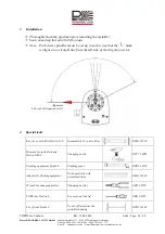
Page 24: ...a way that the mark is aligned in a straight line from the left side of the irrigation sector 4 Special tools Key for coarse filter Hydra L S Disassembly of coarse filter RZG2 14130 Retainer for spri...

Page 25: ...sing Manual opening by turning the screw for Manual opening to the position between AUTO and OFF approx 1 revolution Sprinkler head rises and begins to rotate Do not stand facing the nozzle opening Se...

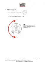
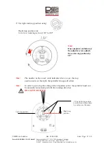
Page 26: ...lefon 0049 7051 162 0 Fax 0049 7051 162 133 E mail perrot perrot de E mail Konstruktion technik perrot de 6 Setting irrigation sector Part circle sprinklers only Set the left side stop position using...

Page 27: ...sector of 30 to 330 330 Note The number on the rotary scale indicates where as per the stop position scale on the right the sprinkler changes direction Note In order to speed up the setting of the ir...

Page 28: ...7 Replacing the nozzle Ensure sprinkler is not under pressure Loosen all 3 of the cover s securing screws and remove cover Using a screwdriver remove white retaining ring Pull sprinkler insert out of...

Page 29: ...162 133 E mail perrot perrot de E mail Konstruktion technik perrot de Put O ring over the new nozzle and reversing the procedure re install in the sprinkler head Fit cover into sprinkler head s snap i...

Page 30: ...is maintained by correctly adjusting the inlet nozzle Adjust as follows Take off inlet nozzle and filter together by using a screwdriver to lever up the inlet nozzle at the notch Snap inlet nozzle bac...

Page 31: ...rot de 7 2 Fitting the sprinkler insert Fit O ring onto flange and lightly grease for easier assembly Fit sprinkler module inside housing WARNING Ensure correct alignment Push flange down as far as it...

Page 32: ...er pressure Loosen all 3 cover securing screws and remove cover Using a screwdriver remove white retaining ring Pull sprinkler insert out of the housing 8 1 Taking out the valve Take off upper and low...

Page 33: ...t Germany Telefon 0049 7051 162 0 Fax 0049 7051 162 133 E mail perrot perrot de E mail Konstruktion technik perrot de 8 2 Taking out the coarse filter only if seen to be dirty Insert valve lifter coar...

Page 34: ...h insert Ensure that thread and O ring are clean Lightly smear O ring with acid free grease Put coarse filter in place and manually tighten using coarse filter wrench 8 4 Fitting the valve Before fitt...

Page 35: ...de Insert lower retaining ring with bumps facing up and fit lower retaining ring rotated by 180 with bumps facing down WARNING Retaining rings must be fully inserted into the slots 8 5 Fitting the sp...

Page 36: ...NG Retaining ring must be fully inserted into the slot Secure housing cover using all three screws Check sprinkler is working properly as per points 5b 5e 9 Control unit removal installation Ensure sp...

Page 37: ...s back WARNING Please ensure that the hoses are fitted in the correct position Otherwise the sprinkler will not work Screw in coil Clip control unit into protective casing Secure housing cover using a...

Page 38: ...nd pressure regulator into the minus position turn to the left as far as it will go and screw in using an SW19 flat spanner Clip control unit into protective casing Secure housing cover using all thre...

Page 39: ...even with manual opening Feeder pipeline under no insufficient pressure Establish pressure supply Coil seat dirty Clean coil seat Bits of dirt between valve seat and sealing plate Clean valve seat an...

Page 40: ...0 Fax 0049 7051 162 133 E mail perrot perrot de E mail Konstruktion technik perrot de F r weitere Informationen stehen wir Ihnen gerne zur Verf gung We remain at your full disposal for any further inf...

Reviews: